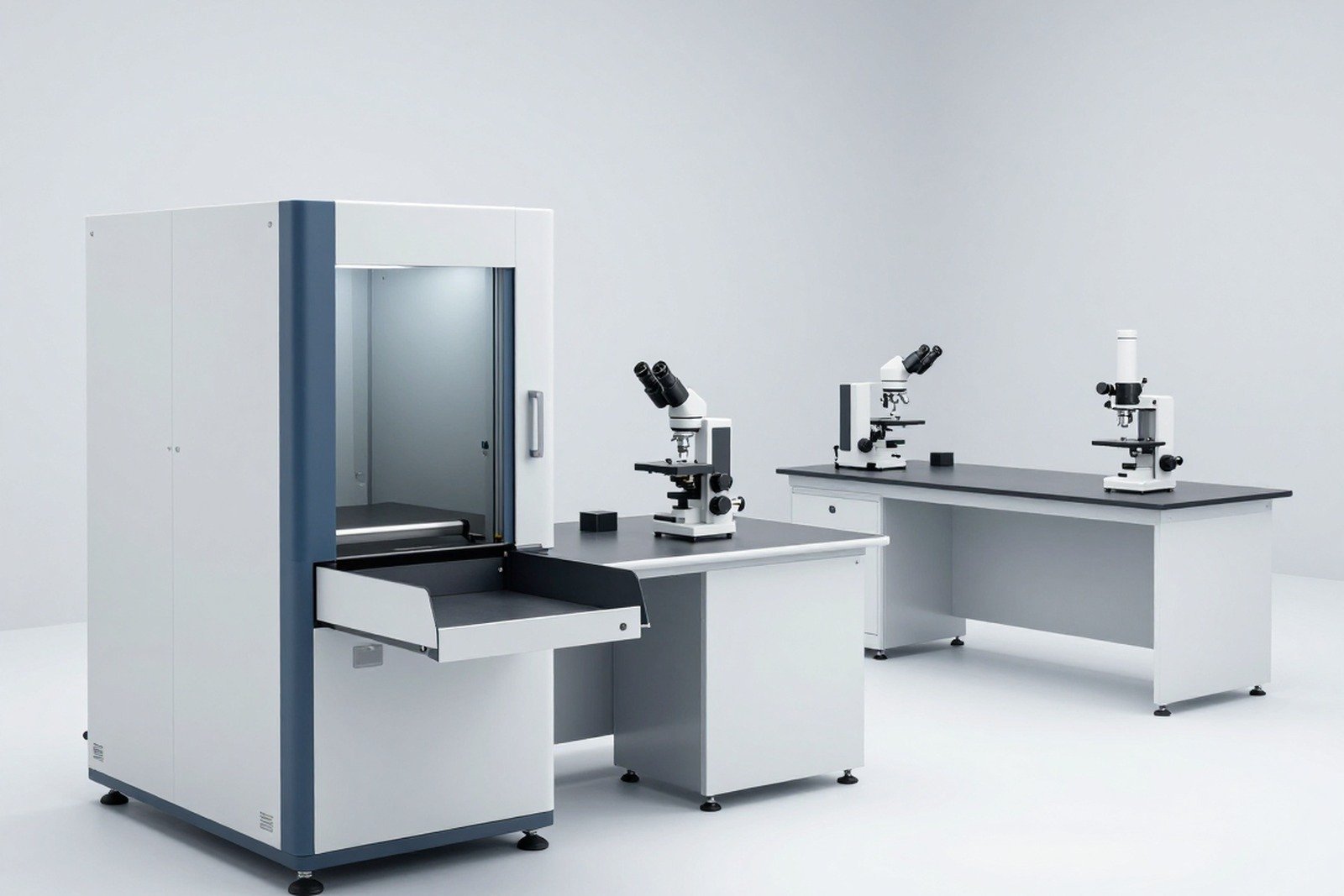
The same four methods are used to “look inside” solder joints and circuit boards, but they answer different questions. Choosing the wrong method often leads to the right result but does not solve the problem at hand.
This article compares cross-sections with X-ray, AOI, and ultrasound scans for each type of question, shows when sample destruction is required, and four common mistakes when choosing a method.
1. Four methods, four different ways of “seeing”.
| Method | How it works | Sample destruction? | The strongest question |
|---|---|---|---|
| AOI (automated optical inspection) | Camera and surface comparison algorithm | No | Missing components, misalignment, solder bridge, wrong direction |
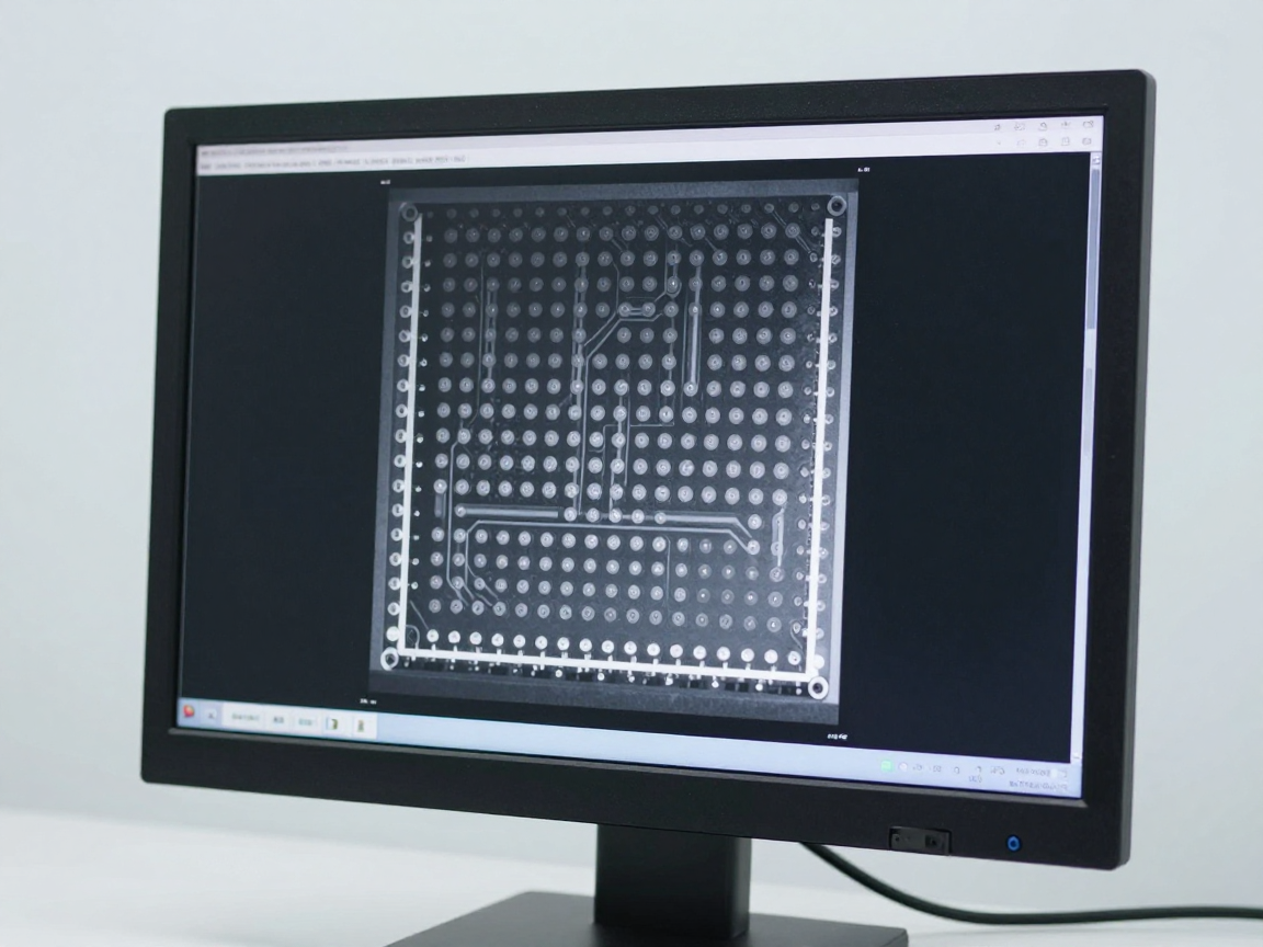
| X-ray | Rays Penetrate materials, creating images according to density | No | Void, missing tin, hidden solder joints under BGA |
| Ultrasound scanning (SAM) | Sound waves reflect at the material interface | No | Layer separation, air bubbles inside the material block |
| Cross-sections | Cut, moulded, ground, polished and then examined the cut surface | Yes | Thickness, penetration, intermetallic compound (IMC) layer, structure |
What the first three methods have in common: they observe indirect signs and do not give reliable size numbers at the microscopic scale. The cross-section does the opposite — it shows the exact cut plane, but at that plane gives direct quantitative information.
2. Method selection table according to questions
| Questions need answering | Suitable method | Notes |
|---|---|---|
| Is the solder joint lacking tin? | X-ray (screening), cross-section (confirmation) | X-ray shows suspicion, cross-section gives conclusion |
| Is the plating thickness in the hole satisfactory? | Cross-sections | Can only be measured on the cross-section |
| Is the circuit board separated? | Ultrasound scan, cross-section | Ultrasound can scan the entire plate and section to confirm the position |
| Are the components in the right position and orientation? | AOI | Visual inspection is sufficient |
| Void in BGA solder joints accounts for what percentage? | X-ray (area measurement), cross-section (plane inspection) | Two methods for two different perspectives |
| How thick is the intermetallic compound (IMC) layer? | Cross-section (with advanced analysis if needed) | There is no alternative non-destructive method |
| Is the error present on the inside or just on the surface? | Combine AOI + X-ray first, cross-section later | This order helps with zoning before cutting |
3. When must the sample be destroyed?
There are four groups of cases where non-destructive methods cannot be an alternative:
- Need thickness numbers: plating layer, coating, intermetallic compound (IMC) layer, dielectric layer. There is no non-destructive method that measures these layers at the microscopic scale with comparable precision.
- Need to confirm link status: The solder joint has formed a metallic bond or just mechanical contact. This is a difference that X-ray cannot distinguish.
- Need legal conclusion or quality dispute: Cross-sectional images with scales are quantitative evidence, stronger than X-ray images when having to explain to a third party.
- Need to analyze the root cause: When it comes to answering “why”, not just “yes or no”.
On the contrary, there are three things that cross-section should not do: inspect 100% of the product, quickly screen the entire batch, and replace AOI or X-ray in routine inspection.
4. Four mistakes when choosing a method
| Mistake | Consequences | How to avoid |
|---|---|---|
| Use X-ray to conclude about plating thickness | Wrong conclusion because X-ray only gives density contrast | Ask measurement questions first, choose methods later |
| Cut the sample before X-ray screening | Waste of samples and costs, can cut in the wrong place | Non-destructive screening first, localization later |
| Conclusion “no errors” from a cross-section | Ignore defects outside the cutting plane | Specify limits and increase number of sampless when risk is high |
| Using ultrasound for unsuitable samples | The resulting noise is due to geometry or materials | Check applicability before submitting samples |

5. Reasonable order: screening first, destruction later
- Visual inspection and AOI: Eliminates obvious surface defects, without wasting samples.
- X-ray: localize the question — what location, what type of solder joint, what level.
- Ultrasound scan (if laminar separation is involved): Determine the scope of defects in the material mass.
- Cross-section at the correct location: get the numbers and final conclusion.
- Advanced analytics if needed: Analyze the composition and structure of the intermetallic compound (IMC) layer.
This order helps each destroyed sample answer the correct question, instead of cutting widely and then discovering it is in the wrong place.
6. Frequently asked questions
Can X-ray replace the cross-section?
No, in the group of questions about size and metal bonding. X-ray is strong in detection and localization; The cross-section is strong in measuring and drawing conclusions about structure.
Can ultrasound scanning replace the cross-section?
Not quite. Ultrasound scanning can inspect the whole sheet and detect good layer separation, but cannot measure the coating thickness or evaluate the intermetallic compound (IMC) layer morphology.
Why not use 3D CT for everyone?
3D CT provides three-dimensional and non-destructive images, but the cost and time are much higher, and the resolution is not always sufficient for the intermetallic compound (IMC) layer. For questions about thickness, cross-section remains the more practical choice.
Is it possible to combine two methods in one report?
This should be done in important cases: X-ray images to demonstrate the defect location, cross-sectional images at that exact location to demonstrate the internal structure.
Which method is fastest?
Fastest AOI in production; X-ray is faster than cross-section but slower than AOI. Cross-section is always the slowest because it has to go through sample preparation.
7. Conclusion
Cross-section, X-ray, AOI and ultrasound scanning do not compete but share the question market. The AOI indicates whether the surface is correct. X-ray shows whether there are internal defects or not. Ultrasound shows whether the material is delaminating or not. Cross-section shows the internal structure correct down to the micrometer or not.
Three things to do: write questions that need to be answered before choosing a method; Always screen non-destructively before cutting samples; and in the report, clearly state which method was used for which conclusion.
References
- IPC-TM-650 Method 2.1.1 — Microsectioning.
- IPC-A-600 and IPC-6012 — Printed circuit board technical requirements and acceptance criteria.
- IPC-7095 — BGA design and assembly, void review.
- IPC-A-610 and J-STD-001 — Weld acceptance criteria.
- Standard for scanning ultrasonic testing of materials and electronic connections.
Related articles
- What is Cross Section? Why do we have to cut samples to evaluate solder joints and circuit boards?
- 7 situations where factories are forced to do cross-sections
- Cross-section BGA: void measurement and head-in-pillow detection
- Choose the cutting position and send the cross-section sample: one wrong step and you will lose the entire data set
Discuss further
Disclaimer
This article is an interpretive content compiled by us; not legal advice. Enterprises need to compare relevant documents/standards verbatim before applying them to specific products.
See more: Copyright Policy & Disclaimer by ticforall.com.