
Void in BGA solder joints is the most controversial topic in electronic quality testing. One side considers every void an error; The other side believes that small voids are a normal characteristic of the procedure. Document IPC-7095 exists to provide a systematic review rather than a perceptive argument.
This article presents the leveled void approach, the correct way to measure it, and what to keep in mind when comparing measurement results with criteria.
1. What is IPC-7095?
IPC-7095 is a guide to the design and assembly of ball bearing components. Content related to quality control covers how to evaluate voids in ball solder joints, including classification by level and different treatments for each level.
| Concept | Content |
|---|---|
| Void | Air bubbles form in the solder joint during the melting process |
| Sort by level | How to evaluate void varies depending on the level and purpose of product use |
| Criteria by position | Voids in critical binding areas are evaluated more severely |
| Scope of application | Used for ball-shaped components and components with large soldering irons |
Note on scope: specific numerical thresholds are specified in the body of the standard document. When applied to specific products, businesses need to compare directly with the standard and agree with customers.
2. Why is void not always an error?
Void forms naturally during the melting process: gases from the flux, moisture and air are trapped as the tin solidifies. So in reality almost every solder joint has a certain amount of void.
What determines whether void is a problem or not are three factors:
- Size: Large void reduces local electrical and thermal conductivity.
- Location: The void located in the area connected to the pad or in the bearing area has a much greater influence than the void in the middle of the tin block.
- Distribution: many small, scattered voids are usually less serious; a large centralized void is the problem.
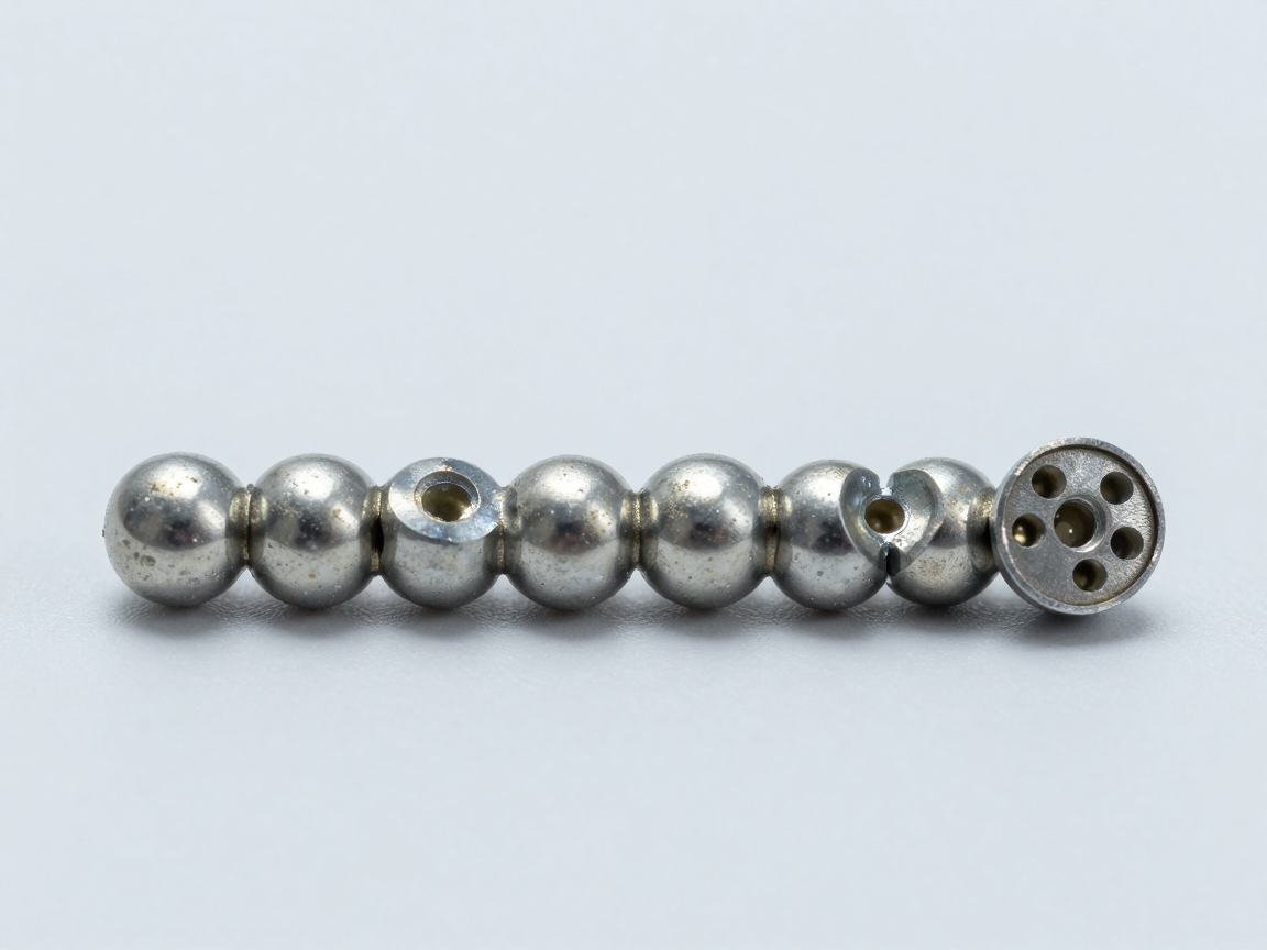
3. How to measure void properly
| Parameters | How to determine | Why is it necessary? |
|---|---|---|
| Ratio of void to total area | Total void area divided by the cross-sectional area of the ball | Reflects the overall reduction in cross-sectional area |
| Largest void size | Measure the diameter or area of the largest void | Reflects the level of stress concentration |
| Void location | Determined by layer: near pad, middle ball, near package | The void in the link area is more important than the void in the middle |
| Large amount of void | Counts the number of voids that are noticeably oversized | Distinguish scattered void from concentrated void |
Indicating a percentage while ignoring size and location is an understatement and often leads to unnecessary disputes.
4. How does Void affect location?
| Void location | Influence | Levels to note |
|---|---|---|
| Located at the interface with the pad | Reduces the bond area, weakening the connection point both mechanically and electrically | High — needs careful assessment |
| Located in the middle of the tin block | Little effect on links if not too great | Lower, depending on size |
| Located on the package side | Affects the link to the pad on the package | High if concentrated |
| Located at the edge of the solder joint | May reveal link borders | Need to consider specific shape |
| Scattered with many small voids | Usually does not significantly affect durability | Low, but need to watch the trend |
5. X-ray and section when comparing criteria
| Method | Let me know | Don’t tell |
|---|---|---|
| X-ray | The ratio of void to the projection of the ball; Check multiple marbles at once | Void position in depth; bond state at the interface |
| Cross-sections | Void position in depth; surrounding link status | Void ratio of the entire row of balls; Only applies to cut balls |
Practical consequence: for the same ball, the void ratio measured by X-ray and the void ratio measured by cross-section may be different. This doesn’t mean one method is wrong — the two methods measure two different quantities. Therefore, the report must clearly state the method used.
6. Evaluation and reporting process
- Determine the applicable level for the product and agree with the customer before measuring.
- Use X-ray for screening and localize balls with large voids.
- Cut the section at the questionable balls, with at least one reference ball.
- Record three parameters for each void: scale, largest size, position.
- Compare criteria by level and clearly state the conclusion for each cut ball.
- State the limit of conclusion: applies to tested balls, does not generalize to all components if there are not enough samples.
7. Common points of dispute
- Difference between ratio measured by X-ray and by cross-section: Due to the nature of the two different measurements, it is not an error.
- Acceptance thresholds vary between customers: Written agreement is required before evaluation.
- Voids in different locations are treated the same: leading to conclusions that are too strict or too lenient.
- Evaluation from just one word: does not represent the entire row of balls or components.
8. Frequently asked questions
Is there a common void threshold for all products?
No. The threshold depends on the level of application, product requirements and agreement with the customer. It is essential to agree on thresholds before testing.
Do small evenly distributed voids need to be reported?
Reporting is recommended to have data to monitor process trends, even if results are still satisfactory.
Does Void progress over time?
It is possible, especially with components working at high temperatures. Void tends to spread with thermal cycles, so the assessment after the heat test has a different meaning than the assessment immediately after solder jointing.
Should I cut the entire row of balls to evaluate?
If the goal is to evaluate uniformity within a row, cutting along that row should be done. If the goal is to confirm a specific location, cutting in the right location is enough.
Can cross-section results be used as evidence?
Yes, the report clearly states the cutting location, measurement method, application level and includes a photo with a scale. These are factors that help verify results.
9. Conclusion
Void is a natural phenomenon of the solder jointing process, not a default sign of error. What needs to be done is a systematic assessment: measure all three parameters, consider the location, and compare with the agreed application level.
Four things to do: agree on levels and thresholds before measuring; Use X-ray for screening and section for confirmation; Record full scale, maximum size and location; and clearly state the limits of the conclusion according to the number of samples tested.
References
- IPC-7095 — BGA design and assembly.
- IPC-A-610 — Electronic Assembly Acceptance Criteria.
- J-STD-001 — Requirements for electrical soldering and electronic assembly.
- IPC-TM-650 Method 2.1.1 — Microsectioning.
Related articles
- Cross-section BGA: void measurement and head-in-pillow detection
- J-STD-001 and IPC-A-610: evaluation of solder joints through cross-section
- IPC-A-600 and IPC-6012: cross-section board acceptance criteria
- Cross-section QFN/DFN: void under the heat sink and solder pins
- Set of standards governing cross-section: IPC-A-600, IPC-6012, IPC-TM-650 2.1.1, J-STD-001 and IPC-A-610
Discuss further
Disclaimer
This article is an interpretive content compiled by us; not legal advice. Enterprises need to compare relevant documents/standards verbatim before applying them to specific products.
See more: Copyright Policy & Disclaimer by ticforall.com.