The two standards most mentioned when talking about solder jointing quality are J-STD-001 and IPC-A-610. They are often used interchangeably, but their roles are different: one specifies process requirements, the other specifies acceptance criteria for inspection.
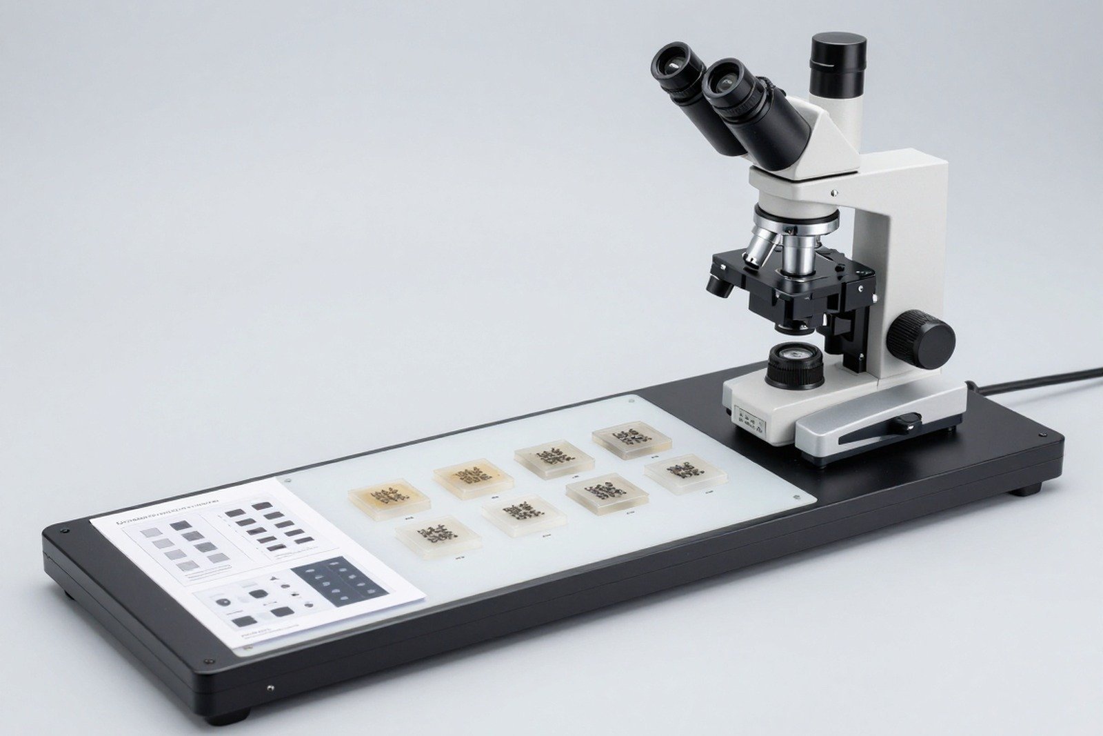
This article explains how to use these two standards when evaluating cross-section solder joints, and what points to keep in mind for a well-founded conclusion.
1. Two standards, two roles
| Standard | Role | When to use? |
|---|---|---|
| J-STD-001 — Requirements for electrical soldering and electronic assembly | Specifies requirements for materials, equipment and processes | When setting up and controlling the solder jointing process |
| IPC-A-610 — Electronic Assembly Acceptance Criteria | Regulations on how to evaluate whether a product passes or fails | When testing and drawing conclusions about the product |
In short: J-STD-001 answers “how to do it”, IPC-A-610 answers “what is considered successful”. A good report should cite both when it comes to assessing causes and quality conclusions.
2. Quality level affects criteria
Both standards are classified by quality level, and the quality level determines the stringency of the criteria. Therefore, the conclusion “satisfactory solder joint” must always be accompanied by the applicable level.
| Granted | Applicable characteristics | Consequences when evaluating |
|---|---|---|
| Level 1 | Requires basic functionality | Some defective characteristics may be acceptable |
| Level 2 | Higher requirements for stability | More restrictions on allowable disabilities |
| Level 3 | Requires high reliability | The strictest criteria, prioritizing ongoing reliability |
3. Welding criteria evaluated through cross-section
| Target | Features to read | Signs to pay attention to |
|---|---|---|
| Fillet shape | Concavity and continuity of the tin surface | Convex surface, broken corners, clear boundaries |
| Foot absorbency | The tin level follows the components | Stick too little or lean to one side |
| Metal bond | There is an intermetallic strip at the interface | No banding or discontinuous banding is seen |
| Cracks in the solder joint | Crack location and direction | Cracks at the heel, cracks parallel to the interface |
| Void | Proportion, maximum size and location | Large void in the bearing area or heat conduction area |
| Gap between pin and tin | Is there a gap between the pin metal and the tin? | Clearance along component legs |
4. Limitations when applying surface inspection criteria to cross-sections
IPC-A-610 is designed primarily for visual and optical inspection of product surfaces. When applied to cross-sectional images, there are three points to note:
- The shape on the section depends on the cutting plane: same solder joint, cut in different position for different shape. Therefore, it is not possible to directly compare the shape on the cross-section with the description of the surface shape.
- Some features exist only on the surface: for example, the gloss or color of the tin surface — things that cannot be read on the cut surface.
- Some features can only be seen on the cross-section: metallic bonds, intermetallic compound (IMC) layers, internal voids — things the surface testing criteria don’t cover.
Correct usage: consider the cross-section as an additional data source, clearly stating which features are read from where, instead of trying to assign all surface criteria to the cross-section image.
5. Procedure for evaluating solder joints on cross-section
- Determine the type of solder joint and the applicable quality level.
- Determine cutting position and direction used, diagram included.
- Read each indicator in the table in section 3 and record the results of each indicator separately.
- Compare with criteria of applicable standards and levels.
- Specify limits: The results only apply to the cut sample, to the selected cutting plane.
6. The role of J-STD-001 in cross-sectional assessment
When the section shows a defect, the next question is whether the defect is of process origin. J-STD-001 is useful at this step because it specifies process requirements: temperature, time, materials, and equipment control requirements.
- Compare actual thermal profile with process requirements.
- Check the type and condition of solder jointing materials and flux.
- Check device condition and calibration status.
- Check cleaning and post-solder joint treatment requirements.
7. Common errors when drawing conclusions
- Apply surface criteria to the cross-section image: leads to wrong conclusions because the two data sources are of different nature.
- No quality level stated: conclusions cannot be compared.
- Conclusion for the whole lot from one sample: a section represents only the plane itself.
- Skip design: has unusual characteristics in shape but conforms to the intended pad and stencil design.
- No reference to standards: The conclusion has no basis for comparison or defense.

8. Frequently asked questions
Is it possible to conclude “pass” based on cross-section alone?
Yes, for the cut sample itself and for the characteristics observed on that cut section. It is not possible to extrapolate to the entire lot from just one sample.
If the shape on the cross-section is different from that described in the standard, how to handle it?
Check the cutting position and direction first. The unusual shape is due to a different cutting plane, not necessarily a defect.
Which quality level should be applied?
According to customer’s request or according to applicable market. This level must be clearly stated in technical documents before production.
Is Void considered an error by the acceptance criteria?
Not automatically. It is necessary to consider the ratio, maximum size, location and requirements of the product. With heat-conducting or load-bearing components, the criteria are often more stringent.
What else should be checked besides the cross-section?
A combination of AOI or optical testing to evaluate surface characteristics, and electrical measurements to evaluate functionality is recommended. Cross-sections add a layer of information that the other two methods do not have.
9. Conclusion
J-STD-001 and IPC-A-610 are not interchangeable: one is about process requirements, the other is about acceptance criteria. When evaluating solder joints through cross-sections, it is necessary to clearly distinguish which characteristics can be read from the cross-section and what limitations this method has.
Four things to do: clearly state standards and quality levels in the report; Do not apply surface criteria to the cross-sectional image; Read each indicator separately and write separate conclusions; and clearly state the limits of conclusions according to the cut sample.
References
- J-STD-001 — Requirements for electrical soldering and electronic assembly.
- IPC-A-610 — Electronic Assembly Acceptance Criteria.
- IPC-TM-650 Method 2.1.1 — Microsectioning.
- IPC-7095 — BGA design and assembly.
Related articles
- Cross-section solder joint: wetting angle, fillet penetration and intermetallic compound (IMC) layer
- IPC-A-600 and IPC-6012: cross-section board acceptance criteria
- IPC-7095: void criteria for level-specific BGA
- Set of standards governing cross-section: IPC-A-600, IPC-6012, IPC-TM-650 2.1.1, J-STD-001 and IPC-A-610
Discuss further
Disclaimer
This article is an interpretive content compiled by us; not legal advice. Enterprises need to compare relevant documents/standards verbatim before applying them to specific products.
See more: Copyright Policy & Disclaimer by ticforall.com.