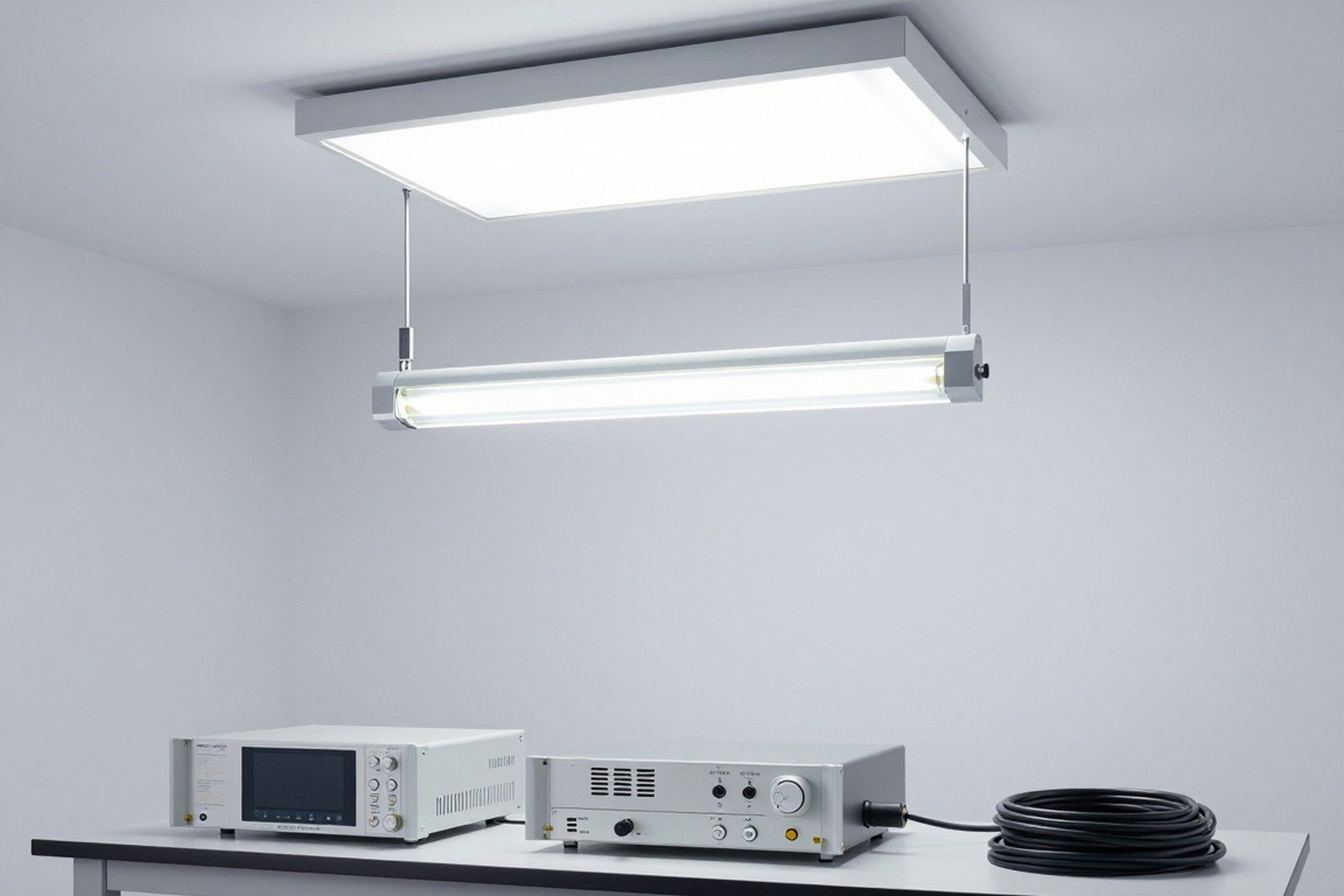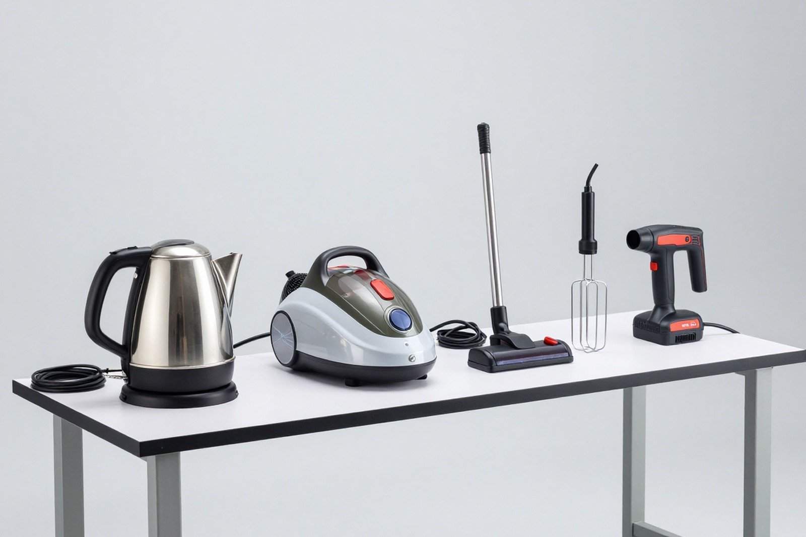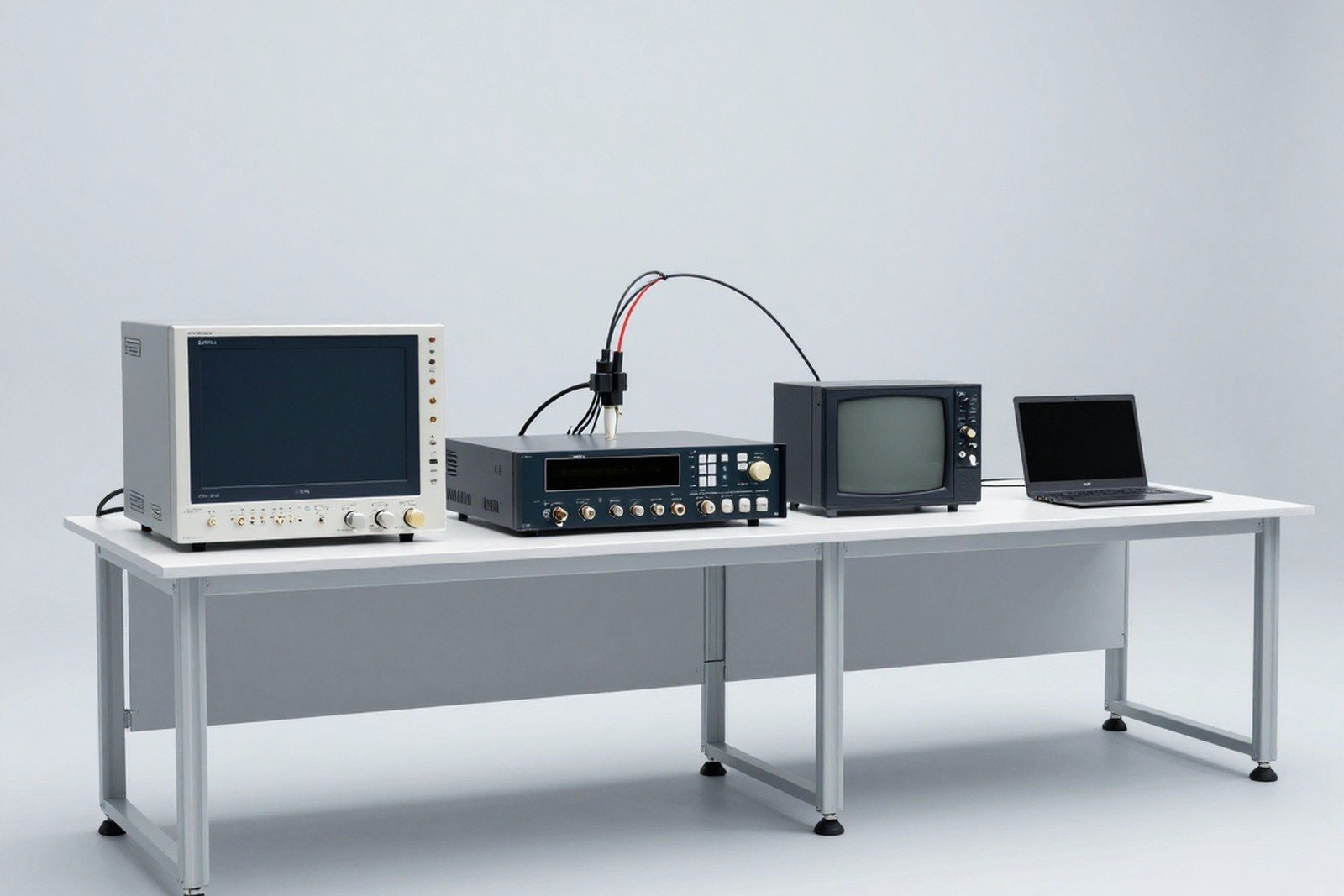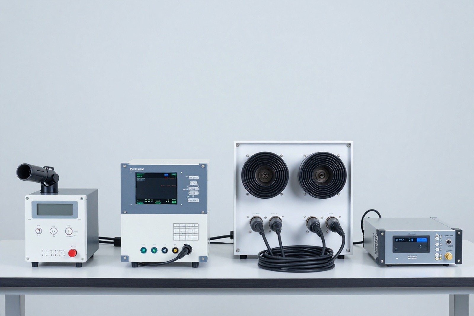
IEC 61000-4 is the “method” part of the IEC 61000 series: it defines interference phenomena, test levels, experimental setup, instruments and evaluation methods for immunity tests and EMC measurements. This is the part that laboratories use every day, and it is also the part that businesses need to understand to know what measurements they are paying for.
1. The role of the 61000-4 group
- Yes basic EMC publication: provides a range of test levels (usually including “X” levels for optional product standards) and standardization methods.
- Do not decide on your own level of application — test levels, pass/fail criteria and operating conditions specified by the product standard or general standard (61000-6-x).
- Guaranteed Results are reproducible between laboratories: same level, same wave, same arrangement must give equivalent results within the allowable uncertainty.
If you want to visualize the whole picture, start from here IEC TR 61000-4-1 — the instruction document is considered a “map” to guide the entire 61000-4 group.
2. Main tests by phenomenon
2.1. Impulsive and transient phenomena
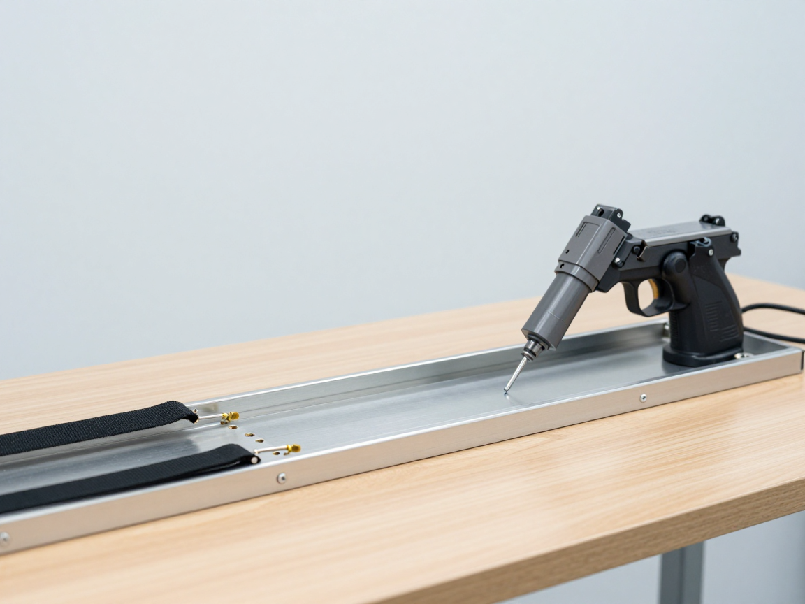
- IEC 61000-4-2 — ESD (electrostatic discharge): simulate electrical discharge from a person or charged object; contact level 2/4/6/8 kV, air discharge up to 15 kV.
- IEC 61000-4-4 — EFT/Burst (fast pulse beam): Fast, low amplitude, high repetition pulses on the power port and signal port; attached to relay contact arc.
- IEC 61000-4-5 — Surge: high energy impulses (lightning, grid switching), form 1.2/50 µs voltage and 8/20 µs current, normal level 1/2/4 kV and “X”.
- IEC 61000-4-12 — Ring waves: Ring-shaped damped oscillating wave, used for indoor low-pressure equipment.
- IEC 61000-4-18 — Damped oscillatory wave: High frequency damped oscillation, used for equipment installed in the station.
2.2. Electromagnetic fields
- IEC 61000-4-3 — Radiated RF fields: most used immunity test, range 80 MHz – 1 GHz and extended to 6 GHz in the current version; Typical levels are 3 V/m or 10 V/m.
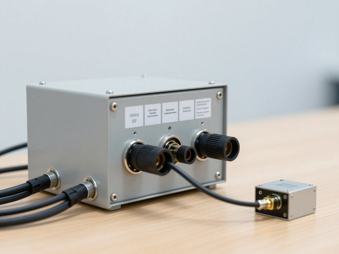
- IEC 61000-4-6 — Conducted RF: Pump RF noise through cable using CDN/EM-clamp, 150 kHz – 80 MHz, typical level 3 V or 10 V.
- IEC 61000-4-39 — Near field: Simulates RF sources located very close to devices (phones, nearby radio devices), wide band up to 6 GHz.
- IEC 61000-4-8/4-9/4-10 — Magnetic fields: 50/60 Hz industrial frequency magnetic field, pulsed magnetic field, damped oscillating magnetic field.
- IEC 61000-4-20/4-21/4-22/4-23: TEM chamber, GTEM chamber, reverberation chamber and testing method in small chamber.
2.3. Supply voltage and power quality
- IEC 61000-4-11 (≤ 16 A) and IEC 61000-4-34 (> 16 A): voltage drop, short interruption and voltage variation on AC source.
- IEC 61000-4-29: voltage drop and short cut on DC power port (devices using adapters, telecommunications devices, battery-powered devices).
- IEC 61000-4-27 (phase imbalance), IEC 61000-4-28 (source frequency variation): specific low frequency immunity tests.
- IEC 61000-4-14 (voltage fluctuation), IEC 61000-4-13 (low-frequency harmonics and mesoharmonics) — the immune side of the low-frequency group.
2.4. Low-frequency measurement and power quality
- IEC 61000-4-7 — Harmonic and mesoharmonic measurements (use with limit 61000-3-2).
- IEC 61000-4-15 — Flickermeter: flicker measurement (Pst, Plt) according to 61000-3-3 and 61000-3-11.
- IEC 61000-4-30 — Methods for measuring power quality Class A and Class S; The 2025 version has 2026 corrections.
- IEC 61000-4-31, 61000-4-41: measurement on large current grids and additional measurement methods.
2.5. Special groups
- IEC 61000-4-16, 4-17, 4-19: low-frequency conducted disturbance, DC power ripple and on-grid signals.
- IEC 61000-4-24, 4-25, 4-32, 4-33, 4-35, 4-36: High electromagnetic pulse phenomenon group to HEMP/HPEM — used for stations, military, and critical infrastructure.
3. What does an immunity test involve?
- Test plan — lists test port, test level, pass criteria, EUT operating mode, monitoring mode.
- Select level and waveform according to product standards; Record all parameters (amplitude, rise time, width, repetition frequency).
- EUT configuration — conductors are placed at the correct length and height as specified, the EUT is connected to auxiliary equipment, and the monitoring software runs continuously.
- Calibrate/check instruments — ESD gun, burst/surge generator, RF pump system, CDN must all have a valid calibration certificate.
- Test run and record — observe both functional criteria and abnormal phenomena; A/B/C conclusion for each port.
4. Performance criteria A/B/C
Each test must include criteria chosen by the product standard. Three familiar levels:
- A: operates as designed during and after interference.
- B: Temporary deterioration, self-recovery after interference stops, no intervention required.
- C: Temporary deterioration, requiring operator reset, but no loss of data and no loss of safety functions.
In fact, many EMC errors are not at the test level but at the test level tracking criteria: If the “worst case” operating mode is not set and there is no monitoring software, the device may have lost functionality and the report will still be successful.
5. Edition updates to know (checked 29 September 2026)
- IEC 61000-4-2:2025 (version 3) replaces 2008 version — adds air-discharge electrode calibration, test point selection appendix and wearable device.
- IEC 61000-4-30:2025 with correction 2026 — updates to Class A/Class S power quality measurement methods.
- IEC 61000-4-29:2026 (version 2) — replace version 2000 for voltage drop/DC power interruption test.
- Recent modifications: 61000-4-23 A1:2025, 61000-4-27 A2:2025, 61000-4-34 A2:2025.
- Commonly used version: 61000-4-3:2020, 61000-4-6:2023 (version 5).
6. Conclusion
IEC 61000-4 is a tool to turn EMC requirements into repeatable measurements: each disturbance phenomenon has a corresponding part of the standard that defines the waveform, level and layout. Understanding group 61000-4 helps you ask the right questions to the lab: What phenomenon should be tested, at what level, according to what version, and evaluated by what criteria? — and those are the three questions that determine the quality of the entire EMC profile.
Related articles
- What is IEC 61000? Overview of electromagnetic compatibility standards
- IEC 61000-4-2: ESD testing — test levels, arrangements and calibration
- What is emission and immunity? EMC platform
- IEC 61000-3-2: current harmonic limits for equipment ≤ 16 A
Talk to us
Disclaimer
The article was compiled by us for interpretation; not legal advice. The standard number and version can be found on the IEC Webstore on September 29, 2026 and may be updated by IEC. Copyright Policy & Disclaimer.