Electromagnetic compatibility (EMC) has two symmetrical halves: emission — devices that cause interference to the surrounding environment, and immunity — the device is resistant to environmental interference. Every EMC test falls into one of these two halves; Correct distinction will help to read the standard correctly, prepare the correct sample and not buy unnecessary measurements.
1. How EMC is defined
According to the common definition in the IEC 61000 series and the electrical engineering dictionary (IEC 60050), EMC is the ability of a device to operate satisfactorily in its electromagnetic environment without causing unacceptable electromagnetic interference to any object in that environment..
This definition contains three important ideas:
- “Satisfactory performance” — EMC does not require that the device be perfect, only that it does not degrade its function excessively when exposed to interference.
- “Environment” — Each type of environment (house, factory, hospital, transformer station) has a different background disturbance level, so the required level is also different.
- “Do not cause unacceptable interference” — there are minor disturbances that are considered acceptable; The limit is that boundary line.
2. Emission — when the equipment is the source of disturbance
Emission is electromagnetic energy that the device generates and releases into the environment. Typical sources: pulse power supplies, inverters, brushed motors, LED lights and drivers, high-clock processors, switching power circuits. Emissions are divided according to propagation path and frequency range:
- Conducted emission: Noise spreads along the power cord, signal wire, and ground wire. Popular measurement range 150 kHz – 30 MHz with LISN (source impedance stabilization network).
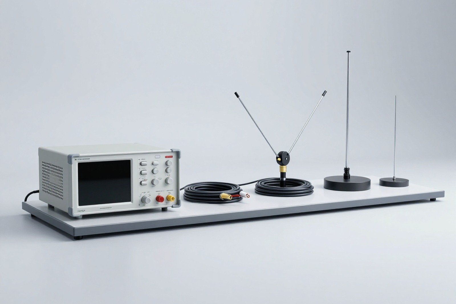
- Radiated emission: interference propagated through space, measured with an antenna in a semi-anechoic chamber or outdoor test site. Common measurement range is 30 MHz – 1 GHz, some standards extend to 6 GHz.
- Low frequency emission: current harmonics and voltage/flicker fluctuations dumped into the grid — fall under group IEC 61000-3.
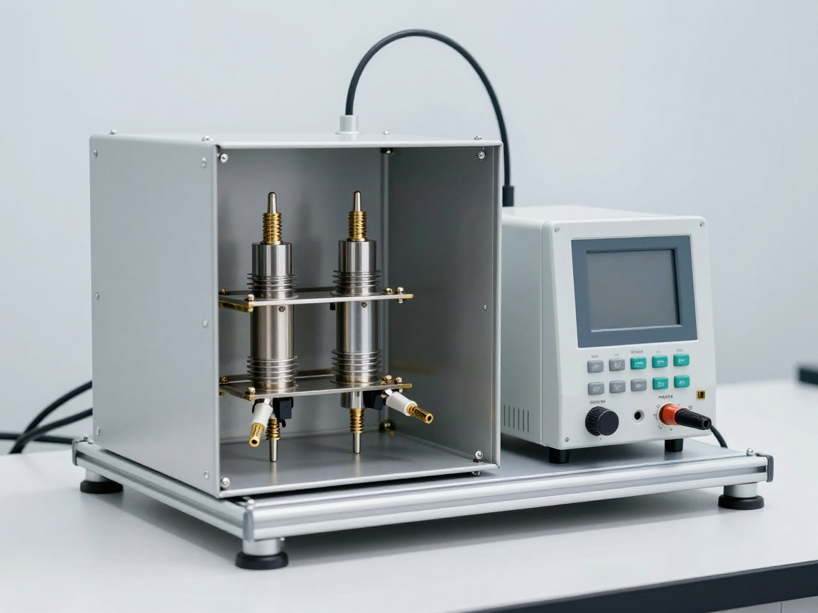
Emission results are typically read as peak levels in measurement mode quasi-peak (QP), and check further average (AVG) when exceeding the QP limit. With devices with short duty cycles, one must run the “worst” working mode to see all the interference.
3. Immunity — when the equipment is the “victim”
Immunity is ability to tolerate interference while still maintaining functionality. The opposite of immunity is susceptibility. A product is considered immune when, under the influence of a specified level of disturbance, it remains within evaluation criteria selected:
- Criterion A: Operates normally during and after interference.
- Criterion B: The function is temporarily impaired but recovers automatically after the disturbance stops, without operator intervention.
- Criterion C: temporarily degrades and requires operator restart or reconfiguration, but retains data and functional safety.
These three criteria are chosen by the product standard, not determined by the 61000-4-x. For the same 4 kV ESD test, a medical device may qualify for criterion A while a household appliance is approved for criterion B — and that makes sense, since the resulting loss of functionality is different.
4. The four combinations and how they are named
Combining the two divisions (conduction/radiation) with the two halves (emission/immunity), we get four common combinations in test reports:
- Conducted emission — for example measuring source-port disturbance according to CISPR 11, CISPR 14-1, CISPR 15, CISPR 32.
- Radiated emission — e.g. field measurement at 10 m in a semi-anechoic chamber according to CISPR 14-1, CISPR 32.
- Conducted immunity — for example RF according to IEC 61000-4-6, DC power ripple according to 61000-4-17.
- Immunity to radiated fields — e.g. radiated RF fields according to IEC 61000-4-3, industrial frequency magnetic fields according to 61000-4-8.
5. Map of frequency ranges and phenomena
- 0 – 2 kHz: current harmonics, voltage fluctuations and flicker, phase unbalance, supply frequency variation (limited to IEC 61000-3-2, 61000-3-3, 61000-3-11, 61000-3-12; methods in 61000-4-7, 61000-4-15, 61000-4-13, 61000-4-14, 61000-4-27, 61000-4-28).
- 2 – 150 kHz: low-frequency conducted disturbance, signal on grid, ripple on DC power (IEC 61000-4-16, 61000-4-17, 61000-4-19).
- 150 kHz – 30 MHz: High-frequency conducted disturbances — half emission specified by CISPR, half immunity specified by IEC 61000-4-6.
- 30 MHz – 1 GHz: Radiated interference and RF field immunity (IEC 61000-4-3; emissions according to CISPR).
- Above 1 GHz: high-frequency emission, immunity to 6 GHz according to 61000-4-3; Devices with nearby RF sources should also consider 61000-4-39.
- Pulse phenomenon: ESD (61000-4-2), EFT/Burst fast pulse burst (61000-4-4), lightning pulse/surge switching (61000-4-5), damped oscillation wave (61000-4-18) — not ranked by frequency band because the energy is very wide.
- Voltage: voltage drop, short interrupt, voltage variation on AC source (61000-4-11, 61000-4-34) and on DC port (61000-4-29).
6. Which quantity is measured?
- Conducted interference: voltage, unit dBµV (level relative to 1 µV).
- Radiation interference: electric field strength, unit dBµV/m or V/m.
- Magnetic field immunity: Magnetic field strength, unit A/m.
- Current harmonics: amperes (A) in harmonic order, or % of base current for lighting equipment.
- Flashing: index Pst (short term), Plt (long term) and voltage change amplitude d, dmax.
7. Which standard covers what?
- Low frequency emission: IEC 61000-3-2, 61000-3-3, 61000-3-11, 61000-3-12.
- High frequency emission: CISPR 11, CISPR 14-1, CISPR 15, CISPR 32 (and industry standard limits).
- Immunity: IEC 61000-4-2 to 61000-4-39 depending on the phenomenon; for multimedia equipment is CISPR 35, for household appliances is CISPR 14-2.
- General standards for “calling” the above parts: IEC 61000-6-1, 6-2, 6-3, 6-4, 6-5, 6-7, 6-8.
8. Three common misunderstandings
- “Emission measurement is complete and EMC is complete”. Incorrect — emission and immunity are two independent sets of requirements; Many markets require both.
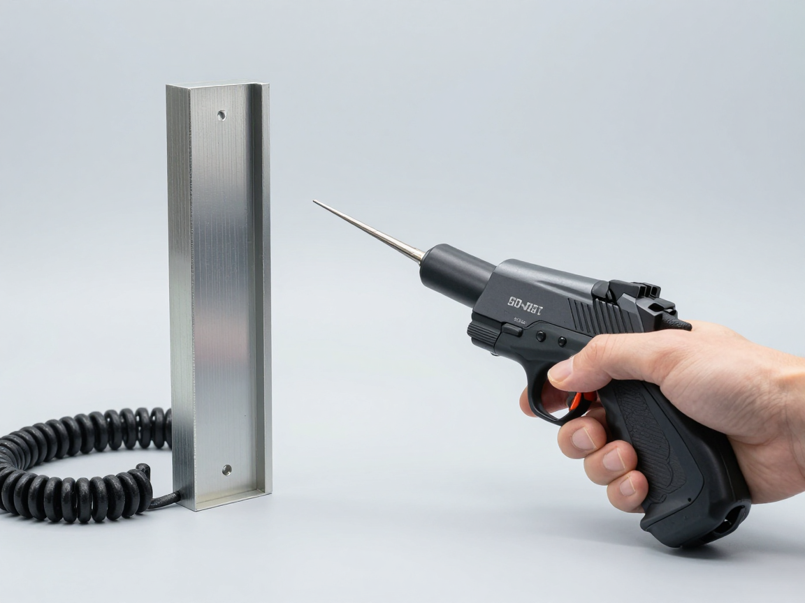
- “ESD, surge, EFT are emissions due to strong impact on the device.” On the contrary, these are tests immunity: device that plays the role of endurance.
- “Achieving CISPR is achieving IEC 61000-3”. CISPR regulates high frequency conducted/radiated disturbances; Harmonics and flicker are still regulated by 61000-3-2 and 61000-3-3, even though they are in the same file.
9. Conclusion
Firmly grasping the two emission-immunity halves and the four conduction/radiation combinations helps to read standards correctly, create correct test lists and correctly understand reported results. The next step is to go into each specific group: IEC 61000-3 for harmonic and flicker limits, IEC 61000-4 for the immunity test method, and CISPR 11/14/15/32 for high frequency emission.
Related articles
- What is IEC 61000? Overview of electromagnetic compatibility standards
- What is IEC 61000-4? Overview of immunity tests
- IEC 61000-3-2: current harmonic limits for equipment ≤ 16 A
- What is CISPR 32? Emission for multimedia devices
Talk to us
Disclaimer
The article was compiled by us for interpretation; not legal advice. Terminology and grouping are based on the IEC 61000 series and IEC Guide 107. Businesses should compare the original standards applicable to specific products. Copyright Policy & Disclaimer.