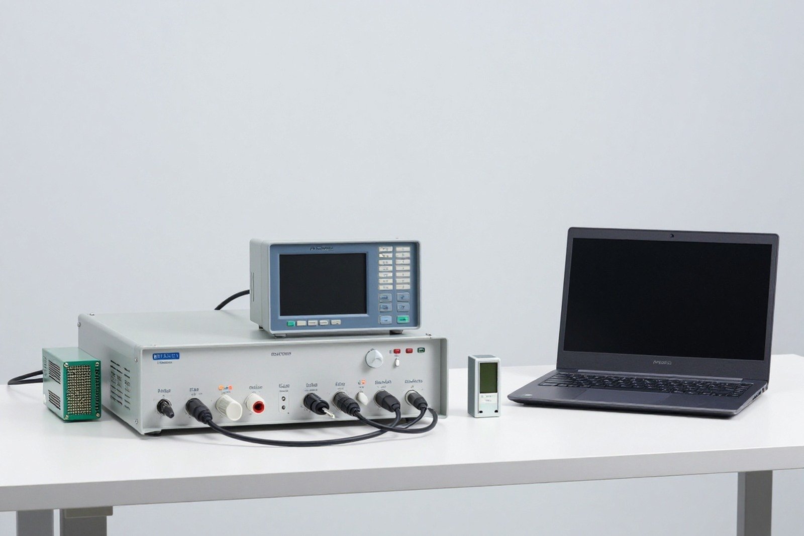
IEC 61000-3-2 is the standard that sets the limit current harmonics which the device feeds back into the public power grid. This is one of the two most mandatory low-frequency standards in the EMC file (along with IEC 61000-3-3 on flicker), and is also the standard that causes many products with pulsed power supplies to be redesigned because they are not “green” enough in terms of current harmonics.
1. Why harmonic currents are limited
Power electronic devices consume non-sinusoidal current: the input current is cut into short pulses, distorted compared to the sinusoidal form of the voltage. That type of distorted current contains many harmonic components (usually odd orders: 3, 5, 7, 9…). Consequences:
- Neutral wire overload — the third and triple harmonics of the phases add together on the neutral instead of canceling.
- Device loss and heat — transformers, condensers, and motors get hotter due to harmonic currents.
- Voltage distortion spreads to other machines — on the same low-voltage grid, one device damages the power quality for the other device.
2. Scope of application
- Applicable to electrical and electronic equipment Nominal input current ≤ 16 A per phase, enter public low voltage grid.
- Applicable to both single-phase and three-phase equipment (with three-phase, the applicable conditions relate to the balanced nature of the load).
- Exclusions equipment with current > 16 A per phase (switch to 61000-3-12) and professional arc welding equipment (switch to 61000-3-12).
- Here it is type test according to the design, without having to check each product on the line.
3. Equipment classification: the four classes
The limit depends on the Class, so the first step is always to determine the Class. Classification in order of priority from D to A:
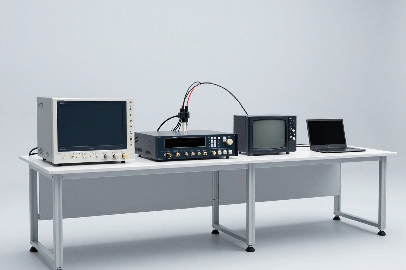
- Class D — equipment with current entering the bearing “special waveform” (wide pulse peak, short time flow) and power ≤ 600 W. Typical examples: personal computers, monitors, televisions, some ICT devices.
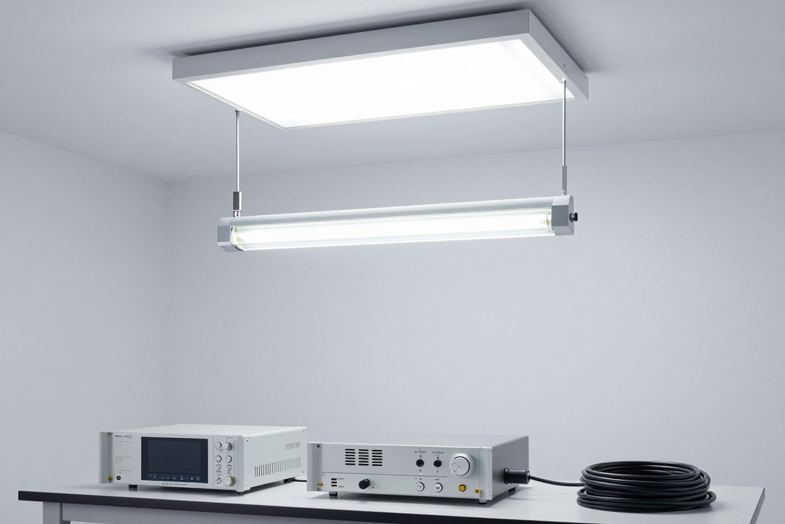
- Class C — lighting equipment: light sets, self-ballasted lights, LED bulbs, drivers, high-pressure lights, street lights.
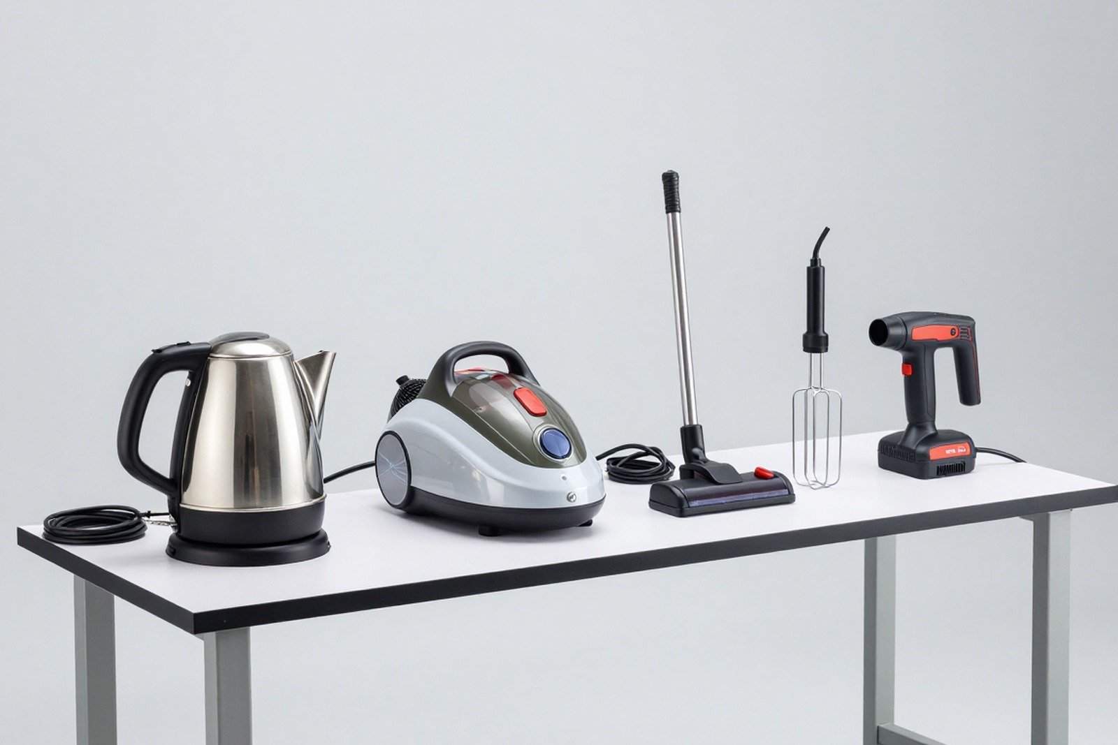
- Class B — hand held electric tools (drills, grinders, hand-held cutters…).
- Class A — all remaining non-B/C/D equipment, including: balanced three-phase equipment, non-D household appliances, non-hand tools, incandescent lamp dimmers, audio equipment.
4. Limits for each class
4.1. Class A — absolute limits in amperes
- Odd harmonic: 3rd order = 2.30 A; 5th order = 1.14 A; 7th order = 0.77 A; 9th order = 0.40 A; 11th order = 0.33 A; 13th order = 0.21 A; 15th order = 0.15 A.
- From level 17 to 39 descending limit: 0.132 — 0.118 — 0.10 — 0.09 — 0.084 — 0.077 — 0.072 — 0.067 — 0.063 — 0.059 — 0.056 — 0.053 A.
- Even harmonic also limited: 2nd order = 1.08 A; 4th order = 0.43 A; step 6 = 0.30 A, and the next even steps decrease in descending order in table 1 of the standard.
4.2. Class B — 150 % of Class A limits
Hand-held power tools are loosened by 1.5 times the Class A limit for each harmonic step, because they operate intermittently and have highly variable loads.
4.3. Class C — limits as a percentage of the fundamental current
- Level 3 = 30·λ % fundamental current, where λ is the power factor of the circuit (usually the power factor of the PFC unit).
- Level 5 = 10 %, level 7 = 7 %, level 9 = 5 %, level 11 = 3 %, level 13 = 3 %, and odd steps from 15 to 39 = 3 %.
- Additional conditions: for lighting devices with current phase angles of certain steps, additional phase angle conditions apply; Lighting equipment with a capacity of ≤ 25 W is exempt from the provisions of the standard.
4.4. Class D — limits in mA per watt
- Capacity limits: 3rd order = 3.4 mA/W, 5th order = 1.9 mA/W, 7th order = 1.0 mA/W, 9th order = 0.5 mA/W, 11th order = 0.35 mA/W, the higher orders continue to decrease (0.296 — 0.257 — 0.226 — 0.199 mA/W for orders 13–19…).
- In parallel, the stream of absolute harmonic Class A limits must not be exceeded corresponding — meaning that even if the mA/W calculation is satisfactory, the Class A ceiling must still be checked.
- The power used to calculate the limit is the active power measured under test conditions.
5. Measurement conditions — the most overlooked part
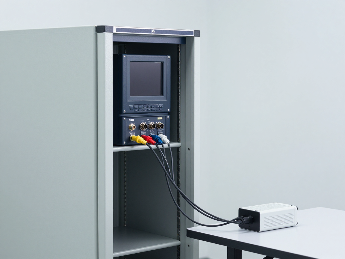
- Measurement method follow IEC 61000-4-7: Use a measurement window of 10 cycles (50 Hz grid) or 12 cycles (60 Hz grid), evaluated according to the average value in the observation range.
- Test voltage and frequency: device identification; With 230 V grid, usually test at 230 V/50 Hz, measured in stable working mode.
- Operating mode: Run the device in the mode for maximum harmonics (usually the largest load, but with some inverter devices it is the average load) — this is the point where a test plan is needed.
- The device has many modes (e.g. inverter refrigerator) must be measured in all modes where excess harmonics may occur, not just the nominal mode.
- Measurement source must have low impedance and small voltage distortion, so that the measured harmonic current is that of the device and not the power grid.
6. A four-step process for a 61000-3-2 file
- Determine Class in the order D → C → B → A based on the function and current waveform characteristics.
- Select test mode for the worst harmonic and clearly state in the test plan (capacity, load, sampling time).
- Measure harmonics according to 61000-4-7 at nominal voltage/frequency, thermally stabilize before measurement.
- Compared to the limit corresponding (absolute, percentage or mA/W) and create a comparison table for each level in the report.
7. Current edition and points to note
- Widely applied version: IEC 61000-3-2:2018 + A1:2020 + A2:2024 (version 5.2, still valid according to IEC Webstore search on September 29, 2026).
- Version 5 expands the scope and clarifies application conditions compared to version 4; Recent revisions add clarity to lighting fixtures and short-cycle handling.
- Current harmonics are only half of the low frequency requirement: equipment remains to be considered IEC 61000-3-3 (voltage fluctuations and flicker) or 61000-3-11/3-12 depending on current and load type.
8. Frequently asked questions
Is equipment with active PFC exempt from harmonic measurement?
Not exempted. Active PFC helps with very small harmonics, but limits must still be measured and compared; In fact, many records use measurement reports to prove success instead of theoretical analysis.
Do products below 25 W have to be tested?
For lighting equipment, the standard has provisions for exemptions for some low-power cases — but the exemption conditions depend on the type of equipment and version of the standard, so you must check the verbatim before drawing conclusions.
How does three-phase measurement differ from single-phase?
With three-phase loads, all three phases must be considered simultaneously; Some balanced three-phase equipment is considered Class A but must still measure harmonics on each phase.
9. Conclusion
IEC 61000-3-2 may seem like just a “limit table”, but the tricky part is define Class and Select test mode. Those two things determine most of the pass/fail results and are also two points that the lab needs to agree on with the customer right from the test plan, before opening the meter.
Related articles
- What is IEC 61000? Overview of electromagnetic compatibility standards
- What is IEC 61000-4? Overview of immunity tests
- CISPR 14-1: emissions for household appliances and power tools
- CISPR 15: interference limits for lighting equipment
Talk to us
Disclaimer
The article was compiled by us for interpretation; not legal advice. The above limits are a common table of values used for illustration; must look up the original table in the standard when filing, as IEC may modify values between versions. Version checked on IEC Webstore on September 29, 2026. Copyright Policy & Disclaimer.