
BGA is a type of component where the entire solder joint is located under the body, cannot be seen with the eye and cannot be inspected with a probe. Therefore, every evaluation of BGA must go through two doors: X-ray to localize, and cross-section to confirm the structure.
This article provides instructions on choosing a row of balls to cut, reading the BGA ball cross-section, measuring void properly, identifying head-in-pillow and the limitations that must be stated when concluding.
1. Why is BGA more difficult to evaluate than regular solder joints?
- Not visible: The solder joint is completely under the component body.
- Unable to check each connection: The number of balls is large, it is impossible to detect each point.
- Defects often lie at the interface: The hardest to observe is where errors often occur.
- Expensive repairs: Disassembling and re-soldering the BGA is a high-risk step, easily damaging the entire board.
2. Select the marble row to cut
| Cutting position | Purpose | Note |
|---|---|---|
| Outer row of balls (package edge) | Evaluate the solder joint in the area subject to the greatest bending stress | Usually the first place where errors appear |
| Row of balls under the center of the package | Evaluate heat and compression zones | This area often has concentrated void |
| Row of marbles near high density areas | Check the influence of neighboring and heat condenser processes | Easily affected by surrounding components |
| Row of balls with high resistance (if known) | Confirm the specific error | Compare with electrical measurement data |
Effective way: cut perpendicular to the row of balls so that the cutting plane passes through the center of the most balls. Oblique cutting distorts the image and any measured numbers no longer represent the true diameter of the ball.
3. Four reading characteristics on the BGA ball cross-section
| Characteristics | Normal signs | Signs to pay attention to |
|---|---|---|
| Ball shape after solder jointing | Evenly flattened at both ends, bulging body is symmetrical | The ball is pulled out of place, unevenly flattened, and the body is distorted |
| Link to pad and to package | There are no gaps at either end | Gaps, clear boundaries, signs of impermeability |
| Void inside the ball | Void is small, scattered | Large void on one side or void cluster in the bearing area |
| The boundary between the ball and the solder paste | Seamless transitions | The boundary is as clear as two separate materials — the head-in-pillow sign |
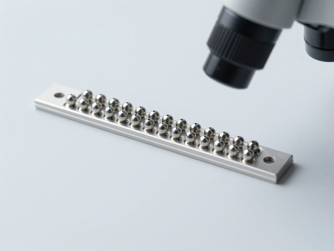
4. Measure the void in the BGA ball
There are three parameters to record, instead of just one:
- Void area ratio on the total cross-sectional area of the ball.
- Largest void size — determines the stress concentration level.
- Void location — located in the pad junction area, in the middle of the ball or on the package side.
| Method | Tell me what | Didn’t say anything |
|---|---|---|
| X-ray | Void ratio on the projection of the entire ball, can check many balls | Void position in depth; bond state at the interface |
| Cross-sections | Void position according to depth, connection condition, ball shape | The void ratio of the entire row of balls, only applies to cut balls |
Because the two methods provide two different types of information, the void ratio reported by X-ray and the void ratio reported by cross-section will not match — this does not mean that either is wrong.
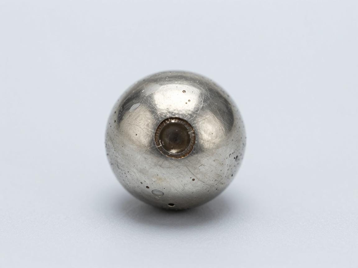
5. Head-in-pillow: identification sign
Head-in-pillow is a situation where the solder ball has melted but the solder paste on the pad has not completely melted, causing the two parts to come into mechanical contact without forming a metal bond. On cross-section, recognizable features include:
- There is a clear boundary between the ball part and the solder paste part, almost two separate blocks.
- The contact surface curves evenly according to the original shape of the ball, not flattening along the pad.
- No intermetallic band is seen at the interface.
- There may be microscopic gaps between the two parts.
Factors commonly associated with head-in-pillow: thermal deformation of the package or circuit board causing the solder joint to separate during melting, oxidation of the solder paste, or insufficient thermal profile for both parts to reach the molten state at the same time.
6. Four other common errors on BGA cross-sections
- The ball is flattened to one side: suggests uneven compression or a misaligned pad.
- Tin bridge between two neighboring balls: confirms the solder bridge that X-ray only suggested.
- Missing package side link: Signs of problems with the pad on the package or the package’s coating.
- Cracks in ball neck: often related to post-solder joint mechanical stress.

7. Five-step process for BGA complaints
- Collect X-ray data of the defective batch and sample to localize the suspect location.
- Compare electrical data If yes: which pin, which board is the error?
- Select cutting position according to the questionable position, accompanied by a row of reference balls.
- Cut and read cross-sections according to the four characteristics in section 3.
- Conclusion separated by each possibility: void, head-in-pillow, solder bridge, or mechanical defects — are not grouped together as “solder joint defects”.
8. Frequently asked questions
X-ray showed a large void, do I need to cut again?
Cutting should be done if the void is located in the bearing area or if the cause needs to be concluded. X-ray confirmed void; The cross-section shows where the void is located and whether the surrounding connections are good or not.
How many marbles are enough to reach a conclusion?
There is no fixed number. There should be at least one row of marbles at the edge and one row in the center, plus a row of control marbles.
Can head-in-pillow be diagnosed by X-ray?
Difficult, because the external shape of the solder joint can still be normal. Even on cross-sections, you need to carefully observe the interface to recognize it.
Should all marbles be cut in one row?
Depends on the goal. If evaluating row uniformity, you should cut along a row to see all the marbles in that row and compare them with each other.
Is a porous solder ball considered a defect?
Not automatically. Need to consider size, location and applicable standards. Small scattered voids are generally accepted; Large voids concentrated in the bearing area are the problem.
9. Conclusion
BGA evaluation requires both X-ray and cross-section: X-ray to know where to look, cross-section to know what is actually there. Sections provide depth information that X-rays do not provide, but only apply to the row of cut balls.
Four things to do: cut perpendicular to the marble row; Select both the edge row and the center row; write void in three parameters instead of one scale; and separate conclusions according to each specific type of disability.
References
- IPC-7095 — BGA design and assembly, content on voids and solder defects.
- IPC-A-610 — Electronic Assembly Acceptance Criteria.
- J-STD-001 — Requirements for electrical soldering and electronic assembly.
- IPC-TM-650 Method 2.1.1 — Microsectioning.
Related articles
- Barrel crack after assembly: causes and proof
- Cross-section solder joint: wetting angle, fillet penetration and intermetallic compound (IMC) layer
- Cross-section QFN/DFN: void under the heat sink and solder pins
- IPC-7095: void criteria for level-specific BGA
- How is Cross Section different from X-ray, AOI and ultrasound? When must the sample be destroyed?
Discuss further
Disclaimer
This article is an interpretive content compiled by us; not legal advice. Enterprises need to compare relevant documents/standards verbatim before applying them to specific products.
See more: Copyright Policy & Disclaimer by ticforall.com.