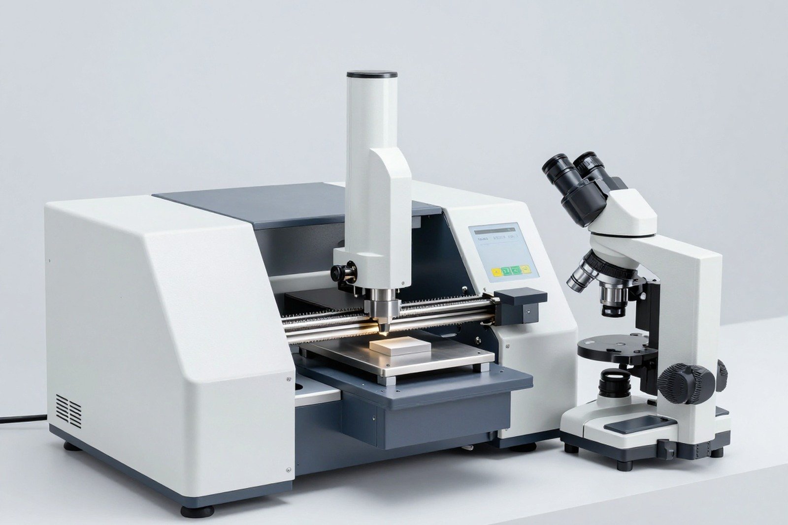
Two testing rooms do the same cross-section but give different results — the reason often lies not in the skills but in the procedure. IPC-TM-650 Method 2.1.1 exists to solve exactly that problem: standardizing how samples are prepared and how microsection testing is performed.
This article describes the role of this test method, the steps to be followed, and the control points that directly affect the results.
1. What is IPC-TM-650 and Method 2.1.1?
IPC-TM-650 is a set of documents that collects test methods for materials and electronic products. Method 2.1.1 in this set specifies how to perform microsection — that is, cutting, molding, grinding, and polishing the sample to observe the internal structure under a microscope.
| Concept | Content |
|---|---|
| Microsection | Sample destruction method to observe the internal structure along the cutting plane |
| Purpose | Check the board structure, solder joints, plating and interfaces |
| Nature | Destructive method, results only apply to cut samples |
| Role of 2.1.1 | Standardize the execution sequence and conditions so that results can be compared between times and between rooms |
Note on scope: detailed specifications (type of abrasive, abrasive sequence, pressure, polishing steps, photo requirements) are specified in the standard text. When applying, businesses need to compare directly with the standard instead of relying on indirect descriptions.
2. Why is process standardization important?
- Results must be comparable: Without a standard process, it is impossible to know whether the difference is due to the sample or the method.
- Destroyed samples cannot be redone: Making a mistake in the preparation step means losing the opportunity to observe.
- Sample preparation can create spurious defects: Scratches, burrs, and fake gaps are all easily read as real defects.
- Conclusions must be verifiable: The third party needs to know in what order the sample was processed.
3. Process steps
| Step | Purpose | Main control point |
|---|---|---|
| Choose the location and cut the pattern | Insert the cutting plane through the area to be surveyed | Cutting direction, speed and cutting force are suitable for the material |
| Clean the sample | Remove impurities before casting | Does not leave residue that affects the adhesion of molded plastic |
| Casting samples | Fix the sample for grinding without deforming it | Suitable molding resin, limiting air and voids |
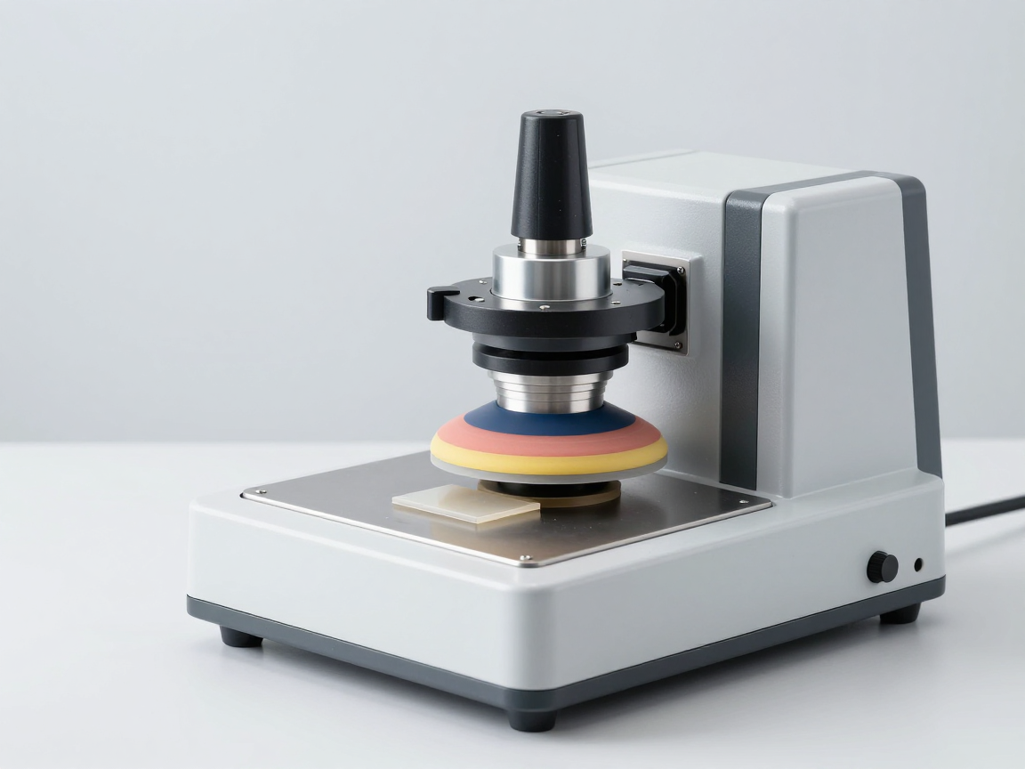
| Rough grinding | Bring the sample face close to the plane to be observed | Pressure and time; Avoid grinding too deeply and losing the survey area |
| Fine grinding and polishing | Remove scratches, create observable surface | The abrasive grain sequence gradually decreases, the pressure gradually decreases |
| Clean and dry | Removes abrasive particles and impurities from the surface | Do not leave particles on the surface before shooting |
| Observe and measure | Record characteristics and measure dimensions | The magnification is appropriate, there is a scale in the photo |
4. Requirements for samples and cutting positions
- The cut location must be representative for the area to be evaluated, do not choose based on convenience.
- The cutting direction must be appropriate with the structure to be observed: longitudinal cutting for through holes, perpendicular cutting of ball rows for ball-shaped components.
- Need control sample prepared under the same conditions to distinguish true abnormalities from normal features.
- Need a background image first to try if the sample will undergo subsequent environmental or mechanical testing.
5. Requirements for equipment and supplies
| Category | Role | Impact when inappropriate |
|---|---|---|
| Pattern cutting machine | Cut without deforming the material | Fake cracks, metal burrs, missing areas to be investigated |
| Casting material | Fixed sample | False gap, sample deflection during grinding process |
| Grinding and polishing supplies | Create observable surface | Scratches, loss of thin layers, distorted planes |
| Optical microscope | Observe and take photos | The interface and thin layer are not visible |
| Measuring device on photo | Measure dimensions with reference | Data cannot be verified |
6. Common errors in practice
- Skip the intermediate step when grinding: jumping from coarse to fine grain to save time, leading to deep scratches that cannot be treated.
- Pressing too hard when grinding: causes burrs and deforms the soft metal layer.
- Do not clean between steps: The remaining abrasive particles from the previous step create new scratches.
- Grinding too deep: removal of the intermetallic compound (IMC) layer or thin coating layer to be evaluated.
- Shoot at only one magnification: Missing overall information or missing details, depending on the magnification selected.
- Do not record the performed sequence: results cannot be reproduced or interpreted in dispute.
7. Take notes so the results can be verified
- Cutting location and direction, with diagram or photo showing location on the product.
- Sequence of grinding and polishing steps performed.
- Magnification of each image and corresponding scale.
- Control sample information and background image, if available.
- Standards and quality levels are used to evaluate results.

8. Frequently asked questions
Is this procedure mandatory?
Depending on customer requirements and applicable quality system. In many cases, the reference to a standardized test method is a condition for the results to be accepted in dispute.
Is it possible to build internal processes yourself?
Yes, but should be based on standardized test methods and clearly state deviations from standards, if any.
Where to get detailed technical specifications?
Taken directly from the test method content in the standard document. This article only presents the general role and sequence.
Does a wrong mold have to be made again?
It often has to be done again, because the sample has been cut and ground. This is why it is important to prepare enough backup samples from the beginning.
Do I need to take photos at multiple steps?
Should be taken at important steps, especially before deep grinding. If a problem is detected, the photos from the previous step help determine whether the cause is in the sample or in the preparation process.
9. Conclusion
The value of the cross-section lies in the reliability of the results, and that reliability depends directly on compliance with the standardization process. A properly prepared sample gives results that are comparable, reproducible, and defensible in the event of dispute.
Four things to do: follow the grinding and polishing sequence, don’t skip steps; Control pressure at every stage; Full recording of cut position, sequence and magnification; and always prepare control samples under the same conditions.
References
- IPC-TM-650 Method 2.1.1 — Microsectioning.
- IPC-6012 — Technical requirements for rigid printed circuit boards.
- IPC-A-600 — Acceptance criteria for printed circuit boards.
- J-STD-001 — Requirements for electrical soldering and electronic assembly.
Related articles
- IPC-A-600 and IPC-6012: cross-section board acceptance criteria
- From rough samples to cross-section images: casting, grinding, polishing and etching
- 5 strange marks on the cross-section: distinguish real errors from phenomena due to sample preparation
- Measuring dimensions on cross-sectional images: how to set the ruler to minimize the error?
Discuss further
Disclaimer
This article is an interpretive content compiled by us; not legal advice. Enterprises need to compare relevant documents/standards verbatim before applying them to specific products.
See more: Copyright Policy & Disclaimer by ticforall.com.