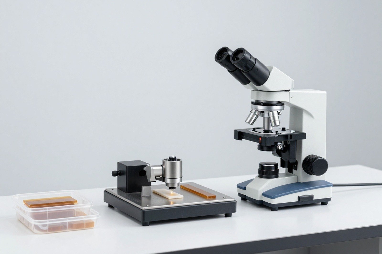
In a set of cross-sectional images, not everything that looks strange is a defect. Cutting, casting, and grinding samples also create marks — and those marks can look a lot like real cracks, real delamination, or faulty solder joints. Mistakes at this point are doubly costly: the factory both goes in the wrong direction and loses credibility with partners when the mistake is discovered.
This article reviews five common strange marks, how to distinguish them from real defects, and what to control during sample preparation.
1. Five strange and common traces
| Traces | The reason is sample preparation | How to distinguish from real errors |
|---|---|---|
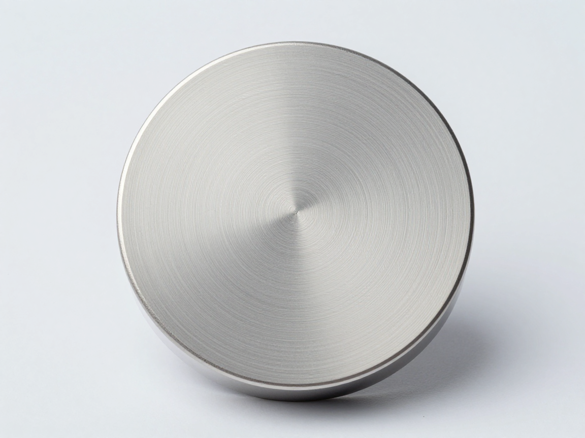
| Parallel scratches | The abrasive grain of the abrasive paper creates grooves on the surface | Parallel, even, only on the surface layer, can be re-sharpened to finish |
| Metal burrs are pulled | Too much pressure causes the soft metal to stick to the cutting edge | The metal strip is long, thin, lying on top of the surface instead of digging into the material |
| Cracking due to shear force | The cutting edge exerts strong impact on brittle materials | Appears from the edge of the sample in, following the cut line |
| False gap due to casting | The molded plastic does not penetrate completely into the small gap, leaving a void | The void has a molded shape, often in a place where penetration is difficult |
| Loss of plating or intermetallic compound (IMC) layer | Over polishing, the thin layer is erased | There is no intermetallic strip visible but there are traces of beveled edges, the thickness gradually decreasing towards the edge |
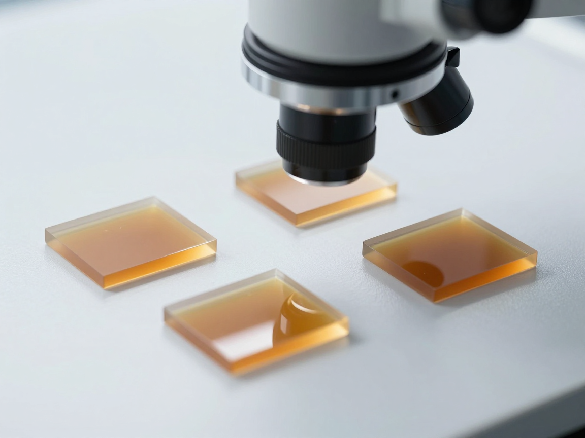
2. General principle of distinction
- Direction: Traces due to sample preparation are usually oriented in the direction of the cutting edge or grinding direction, not in the direction of structural stress.
- By location: Traces due to sample preparation are usually located in the surface layer or at the edge of the sample, rarely deep in the material.
- According to repetition: If you grind again and the mark disappears, there is a high possibility that it is a machining mark. The real error remains after resharpening.
- By form: True defects often have clear edges, sometimes with associated secondary traces (oxidation, deformation, adjacent voids); Machining traces are usually clean, even, and unidirectional.
- According to control sample: Compared with well-prepared samples, machining traces tend to be similar across many samples, while true errors are unevenly distributed.
3. Transition rim — the easiest place to get confused
The transition zone between materials is where many real defects are concentrated, but it is also where the grinding process easily creates burrs and drag marks. This is an area that needs to be observed at high magnification and compared with many samples before drawing conclusions.
Signs of burrs in this area: soft metal is pulled over the surrounding harder material, creating the feeling of an unusually thick layer of metal. If polished again at a lighter step, this layer disappears.
4. Control points when preparing samples
| Step | Control point | Consequences if done wrong |
|---|---|---|
| Cut the pattern | Choose the right blade for the material, control the speed and cutting force | Fake cracks, metal burrs |
| Casting samples | Use vacuum casting or cold casting, gas control | False gap, void that looks like void |
| Rough grinding | Control pressure and time | Loss of thin plating layer, erasing the area to be investigated |
| Polishing | Using a gradually decreasing abrasive strip, lightly polish | Scratches, scratched metal surfaces |
| Clean | Wash off abrasives and impurities before shooting | Particles stuck to the surface look like defects |
| Take photos | Enough light, enough magnification, with scale | Difficult to assess size and morphology |
5. Checklist before concluding
- Re-sharpened and checked to see if the marks are still there or gone.
- Compared with the control sample prepared under the same conditions.
- Checked whether the direction of the trace was in the structural direction or in the machining direction.
- The possibility of abrasive grains or metal burrs has been ruled out.
- Observed at high magnification at the transition zone.
- Suspicious traces were clearly noted in the report instead of ignored or confirmed.
6. Frequently asked questions
How do you know if a crack is real or caused by cutting?
Grind again and observe. If the crack remains and its direction is related to the structure, it is a true crack. If lost or changed in the direction of grinding, it is a machining mark.
Could the gap between the coating and the surface be due to casting?
Yes. If the molding resin does not penetrate completely into the small gap, it will leave a gap that looks like peeling. It is necessary to distinguish by the shape of the void and the degree of filling in the adjacent area.
Is loss of intermetallic compound (IMC) layer a solder jointing error?
Not always. The intermetallic compound (IMC) layer is very thin so it can easily be erased when polished too hard. It is necessary to check for signs of chamfering at the edge and compare it with a sample prepared more gently.
How many samples should be used to make a clear distinction?
Three samples are a reasonable minimum: if the same mark appears in all three and all have the same orientation, it is likely to be a machining mark. Real errors usually do not repeat exactly the same way.
If still not sure, what is the conclusion?
Record the level of certainty in the report and clearly state the suspected traces, with on-site photos. An honest statement of uncertainty is more valuable than a definitive but wrong conclusion.
7. Conclusion
The quality of a cross-section report depends not only on image reading skills but also on sample preparation discipline. Machining traces can lead to wrong conclusions, and wrong conclusions lead to wrong corrective actions — much more expensive than the initial cost of properly preparing the sample.
Four things to do: always re-sharpen to confirm the mark; eliminate burrs and abrasives before concluding; Prepare at least three samples to evaluate repeatability; and clearly state points of doubt instead of over-confirming them.
References
- IPC-TM-650 Method 2.1.1 — Microsectioning, sample preparation section.
- IPC-A-610 — Electronic Assembly Acceptance Criteria.
- IPC-6012 — Technical requirements for rigid printed circuit boards.
- J-STD-001 — Requirements for electrical soldering and electronic assembly.
Related articles
- From cross-sectional image to root cause: 5 investigation steps
- Two Laboratories, Two Different Results: Why?
- From rough samples to cross-section images: casting, grinding, polishing and etching
- 10 circuit board defects can only be detected by cross-section
Discuss further
Disclaimer
This article is an interpretive content compiled by us; not legal advice. Enterprises need to compare relevant documents/standards verbatim before applying them to specific products.
See more: Copyright Policy & Disclaimer by ticforall.com.