
There is a group of board defects that all non-destructive testing methods miss: structural defects. They are located inside the material, underneath the component base, or at the interface between layers — places where X-ray, AOI, and electrical measurements are unreadable.
This article summarizes 10 such errors, with identifying signs on cross-sectional images and reasons why other methods cannot detect them.
1. Ten errors can only be seen by cross-section
| # | Error | Marks on the cross-section | Why is it difficult to see otherwise? |
|---|---|---|---|
| 1 | Cracked into plated holes | Cracks in the plating layer form holes | Located along the depth, X-ray only shows when the crack is large enough and in the right direction |
| 2 | Do not wet the solder joint | Broken boundary between tin and surface | Located at the base of the component, not visible from above |
| 3 | Head-in-pillow | Clear boundary between ball and solder paste, no metallic bond | The external appearance is completely normal |
| 4 | The intermetallic compound (IMC) layer is unusually thick | The intermetallic strip is thick and wavy at the interface | Does not affect the appearance of the solder joint |
| 5 | Void under the heat sink base | Large air bubble in the soleus area | X-ray shows but cannot determine position in depth |
| 6 | Separate the base material layer | The gap between the layers of material in the circuit board | Located in solid material, there is no optical signal |
| 7 | Circuit breakage due to heat | The circuit is broken, the edges show signs of burning | Seen by electrical measurement but can’t see the cause |
| 8 | Cracked multi-layer ceramic capacitor | The oblique crack originates from the corner near the solder joint | The crack is inside the condenser body, not exposed |
| 9 | Peeling off protective coating | Gap between overlay and board surface | Only the peeling edge is seen, no level of adhesion is seen |
| 10 | Lack of copper in the plating hole | Plating thickness is uneven and locally thin | It is impossible to measure the plating thickness in the middle of the hole without cutting |
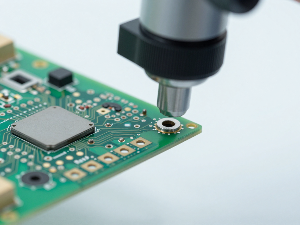
2. Error group belongs to the solder joint
This is the most common group and is also the main reason why factories make cross-sections periodically. Common point: all links are hidden.
- No wetting: The tin is adjacent to the surface but not bonded. The cause is usually surface contamination or oxidation.
- Head-in-pillow: The two tin parts come into mechanical contact without forming a bond. This is the most difficult error to diagnose in this group.
- Thick or broken intermetallic compound (IMC) layer: The bond is formed but the quality is not met, leading to brittleness or a cracking initiation point.
- Large void at the bearing position: void itself is not a defect, but large voids in the right position reduce durability and heat conductivity.
3. Error group belongs to the circuit board
- Cracked into plated holes: The most severe structural error of a through-hole solder joint, causing loss of connection between layers.
- Lack of copper in the hole: The plating thickness is below the required level, causing local overheating when large current flows through.
- Separating the base material layer: Gaps between layers of material, often related to solder jointing temperature or residual moisture in the material.
4. Error groups belong to components and coatings
- Cracking of multi-layer ceramic capacitors: Cracks form due to bending stress, which may not appear until moisture penetrates.
- Peeling off protective coating: The coating does not adhere well enough, allowing moisture and impurities to penetrate over time.
- Circuit breakage due to local heat: The cross-section shows that the cause of the break lies in the heat, not in the overload current.
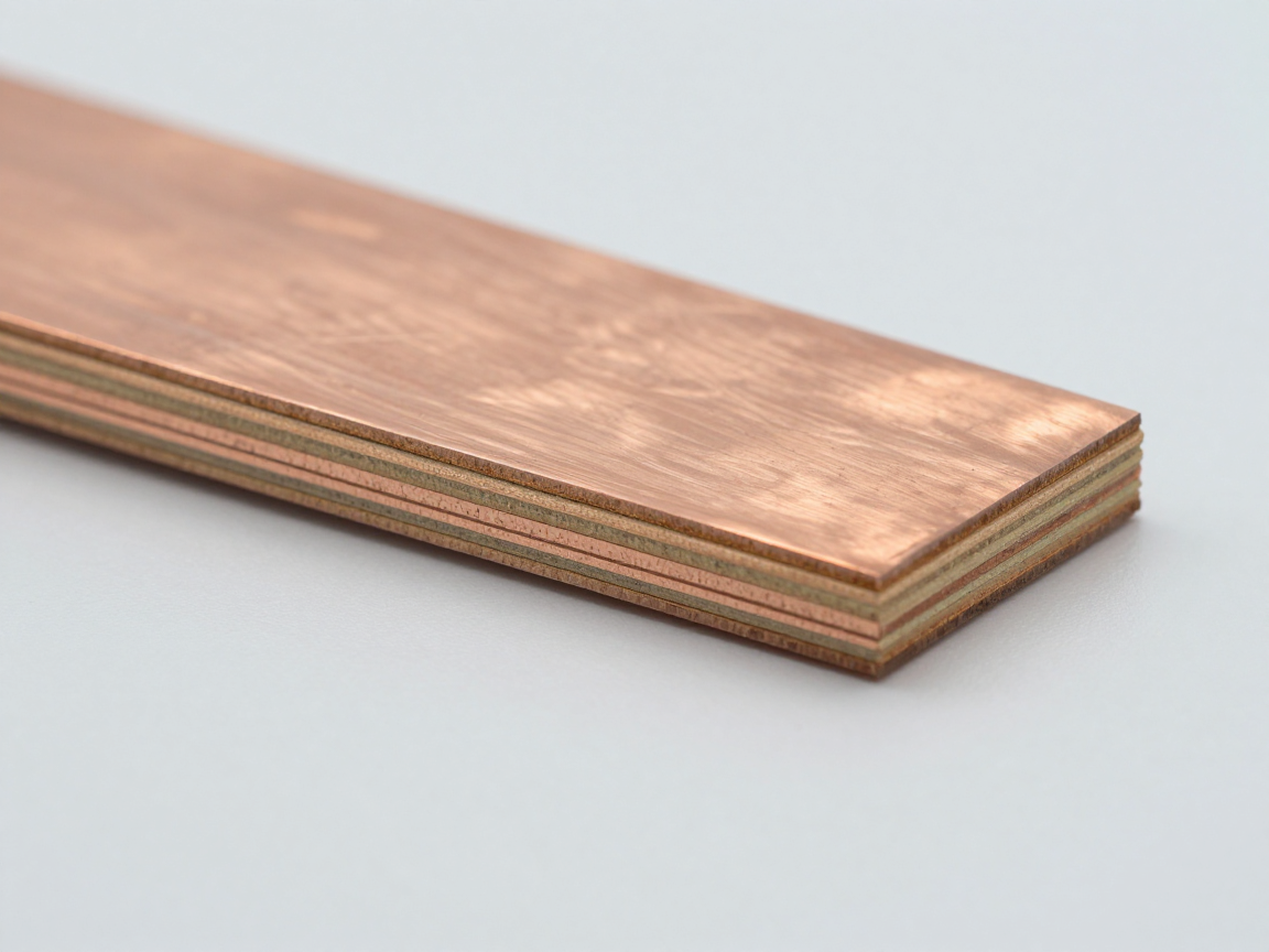
5. Why can’t other methods detect it?
| Method | Strengths | Blind spot with the above error group |
|---|---|---|
| Visual inspection, AOI | Fast, can check the entire surface, detect shape errors | Do not see any hidden or embedded parts in the material |
| X-ray | Can see through the component body, detect voids and tin content | Cannot distinguish layers by depth; Metallic bonding cannot be evaluated |
| Ultrasound | Detect delamination and voids in materials | Welds with pins cannot be evaluated; requires a suitable sample |
| Measure electricity | Confirm whether the circuit is open or not | No open circuit error is seen; does not indicate the cause |
| Cross-sections | See the structure in depth, measure the true size | Only applies to cut samples, cannot test the entire batch |
The role of cross-section is not to replace the other methods, but to supplement the layer of information that they do not have: internal structure and interface.
6. When should you proactively cut off inspection?
- The first batch of a new product or a new process.
- After changing the supplier of circuit boards, solder paste, components or thermal profiles.
- When there are complaints about operational errors but electrical measurements cannot find the cause.
- After a field problem there are signs that accumulate over time.
- Periodically follow the quality control plan, even when there are no problems.

7. Frequently asked questions
Is there any method to replace cross-section?
No method gives equivalent results regarding the internal structure. Optical tomography can be used for transparent samples, but is not suitable for circuit boards and metal components.
Does cross-section destroy the pattern?
Yes, the model is cut and molded so it cannot be returned to production. This is why it is important to choose a highly represented cutting location.
With a product running well, is it necessary to cut and check?
Should be done with the first batch and when there are process changes. Working well in the early stages does not eliminate errors that accumulate over time.
Which error should we focus on in the list above?
Depending on the product. Multi-layer circuit boards with through holes should focus on plated holes; Products with BGA components should focus on the head-in-pillow and void groups; Products with many ceramic capacitors should pay attention to cracks due to bending.
Are the sectional results conclusive for the whole batch?
Not directly. Sectional results only apply to cut samples. To draw conclusions for a batch, it is necessary to combine process data, other test data and the appropriate number of samples.
8. Conclusion
The ten defects in this article have one thing in common: they are located where light, X-rays, and electric current cannot reach. That’s why cross-sections still play an irreplaceable role in electronic quality control.
Four things to do: build a separate list of critical errors for each product; cut inspection at the first batch and after each process change; Always cut with a control sample; and combine cross-sectional results with process data instead of drawing conclusions from images alone.
References
- IPC-A-610 — Electronic Assembly Acceptance Criteria.
- IPC-6012 — Technical requirements for rigid printed circuit boards.
- IPC-TM-650 Method 2.1.1 — Microsectioning.
- J-STD-001 — Requirements for electrical soldering and electronic assembly.
Related articles
- What is Cross Section? Why do we have to cut samples to evaluate solder joints and circuit boards?
- How is Cross Section different from X-ray, AOI and ultrasound? When must the sample be destroyed?
- From cross-sectional image to root cause: 5 investigation steps
- 5 strange marks on the cross-section: distinguish real errors from phenomena due to sample preparation
- Set of standards governing cross-section: IPC-A-600, IPC-6012, IPC-TM-650 2.1.1, J-STD-001 and IPC-A-610
Discuss further
Disclaimer
This article is an interpretive content compiled by us; not legal advice. Enterprises need to compare relevant documents/standards verbatim before applying them to specific products.
See more: Copyright Policy & Disclaimer by ticforall.com.