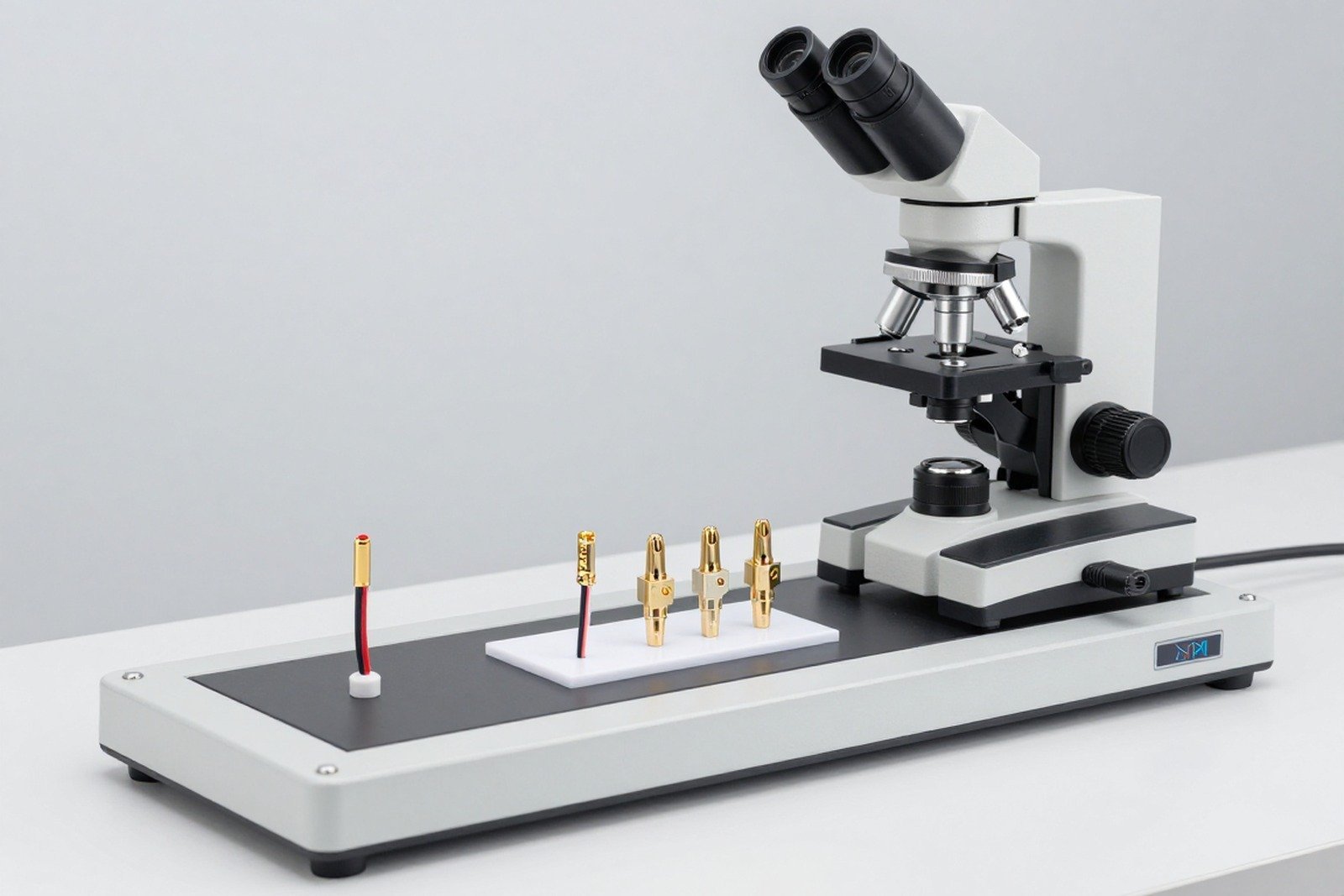
The wire connection to the connector is not soldered but mechanically compressed. That means everything that determines the quality of the joint is inside the tube body, and no external test can read it. The section is the only tool that sees the part.
This article teaches you how to read cross-sections of the crimp terminal, evaluate compression, broken strands, gaps and four common injection mold errors.
1. Why must pressure joints be evaluated by cross-section?
- The link is inside the squeeze tube: cannot be observed from the outside.
- Appearances can be deceiving: A strong-looking crimp may still hold fewer strands of wire than designed.
- Injection mold error only appears when dissecting the sample: Mold wear, wrong size or eccentricity cannot be detected by eye.
- Consequences appear late: Poorly pressed joints increase contact resistance, causing local heating and corrosion over time.
2. The structure needs to be read in section
| Ingredients | What to evaluate? | Signs to pay attention to |
|---|---|---|
| Pressure tube body | Deformation level and symmetry | Pressed on one side, the tube does not close evenly |
| The wires inside | Deformation level and uniformity between fibers | Fibers are overly compressed to become flat, or have fibers that are not deformed |
| Transition zone outside the tube | Flared mouth shape and fiber continuity | The mouth of the pipe cut into the wire |
| Insulated clamp part | Clamp position relative to wire sheath | Clamp to the wire core instead of the sheath, or do not clamp to the sheath |
| Space in the tube | The filling level of the wire in the tube | Large gap on one side or in the center |
3. Evaluate compression
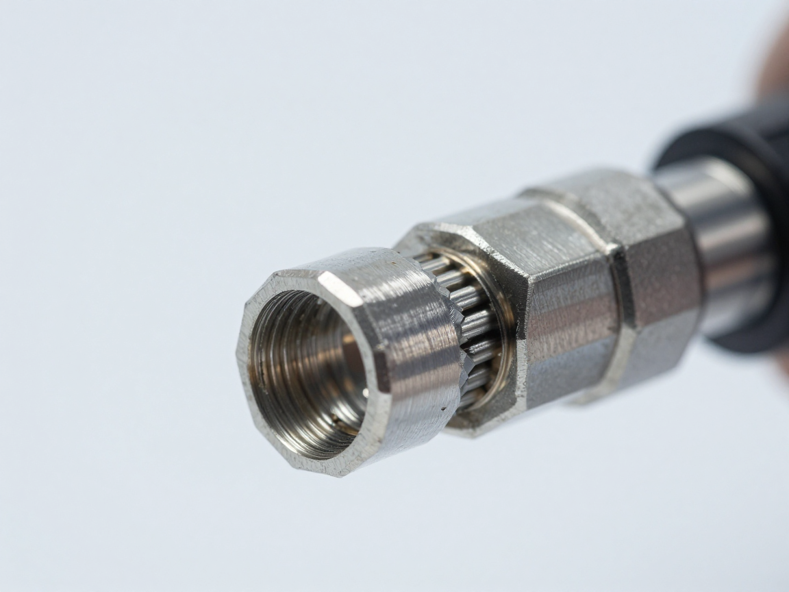
Compression represents the degree of deformation of the wire when pressed by the mold. How to evaluate on cross-section:
- Distortion level: Are the strings flattened and pressed together or still keeping their circular shape intact?
- Uniformity: Does all the ropes deform, or only some of them bear the force?
- Symmetry: The compression level is evenly distributed around the pipe circumference or concentrated on one side.
- Fill level: How far is the volume inside the tube filled by the string?
| Status | Marks on the cross-section | Implication |
|---|---|---|
| Enough compression | The wire is evenly flat, filling the tube completely, without large gaps | The connection is mechanically and electrically satisfactory |
| Compression is not enough | Many fibers still retain their round shape and have empty space | High contact resistance, easy to loosen when vibrated |
| Excessive compression | The wire is strongly flattened, has broken strands, and has a reduced cross-sectional area | Reduced electrical conductivity and tensile strength |
| Deviation compression | One side is strongly compressed, the opposite side still has space | The mold is off center or the crimp terminal is misaligned |
4. Broken wire rays and gaps
These are the two most important criteria when evaluating pressure joints:
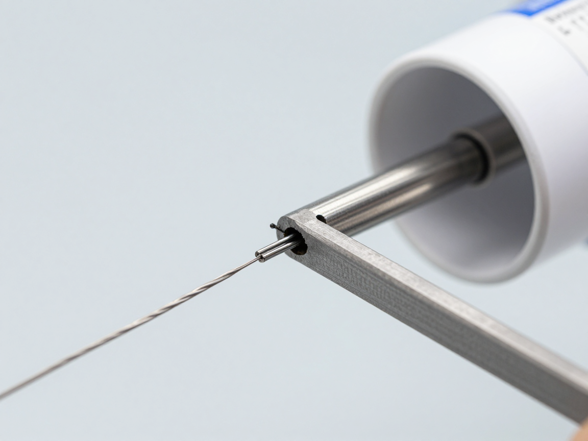
- Broken wire beam: The wire is cut off by the mold, reducing the actual conductive cross-section. The number of broken strands allowed depends on the applicable standard, quality class and number of strands of the wire.
- Space: the area not covered by the wire in the tube. The voids create a way for moisture and impurities to penetrate, leading to galvanic corrosion and increased contact resistance over time.
Correct way to record: count the number of broken fibers at each location, clearly state the total number of fibers in the wire, and describe the location of the gap (at the mouth of the tube, at the center, or on the opposite side of the compression point).
5. Four common injection mold errors
| Error | Marks on the cross-section | How to handle |
|---|---|---|
| Using the wrong mold size | Excessive or insufficient compression on the same wire gauge | Check the mold selection table according to wire size and crimp terminal size |
| Mold is worn | The pressed joint is not closed, burrs or gaps appear between the two halves of the mold | Re-measure mold size and replace periodically |
| Eccentric pressing | One side is strongly compressed, the opposite side is not compressed | Check mold alignment and crimp terminal position |
| Insulation clamp in wrong position | Clamps to the wire core or does not clamp to the wire sheath | Check the wire position in the crimp terminal before pressing |
Point to remember: these four errors are all invisible to the eye and can only be determined by cross-section. Therefore, periodic cross-section inspection is a more effective means of mold control than relying on visual inspection.
6. Additional testing should be combined
- Pull force test: Measure the force that breaks or loosens the joint and compare it to the standard.
- Measuring contact resistance: detect joints with insufficient conductive cross-section.
- Vibration test and thermal cycle test: Evaluate the stability of the joint under operating conditions.
- Salt mist corrosion test: Evaluate the ability to resist penetration of moisture and impurities through gaps.
7. Frequently asked questions
Does a pressure joint that achieves traction mean it achieves all aspects?
Not really. Pressed joints can achieve tensile strength but still have voids inside, leading to corrosion in the long run. These two indicators complement each other and do not replace each other.
How many broken threads are considered defective?
Depending on applicable standards, quality level and number of strands of wire. What needs to be done is to clearly state the total number of threads and the number of broken threads, then compare them with the agreed criteria.
Do small multi-strand ropes and large few-strand ropes have the same evaluation?
No. Small multi-strand ropes need to evaluate the uniformity between the strands; In a wire with several large strands, each broken strand has a much larger effect on the conduction cross-section.
Is there a way to check pressure joints non-destructively?
X-ray can be used to see the shape of the tube body and the filling level, but it is not enough to conclude about fiber deformation and number of broken fibers. The cross-section is still needed for the final conclusion.
Where should the sample be cut on the pressure joint?
Cut along the axis of the cose head to see the entire length of the tube, the transition part and the insulating clamp part in the same section.
8. Conclusion
The wire connection is mechanically compressed so its quality is only apparent when dissecting the sample. The three things to read are compression, broken strands, and clearance — all three of which cannot be assessed by eye or by inspection of appearance.
Four things to do: cut along the axis to see the entire joint in one section; clearly state the total number of threads and the number of broken threads; Always include the results of the traction force test and contact resistance measurement; and periodically check injection molds because this is the most common source of errors but the hardest to detect.
References
- IPC/WHMA-A-620 — Requirements and acceptance criteria for cable and conductor assemblies.
- IPC-TM-650 Method 2.1.1 — Microsectioning.
- Technical standards for crimp terminals and injection molds of the manufacturer.
- UL 486A-486B — Standard for wire connectors, press splice requirements section.
Related articles
- QCVN 4:2009/BKHCN: safety requirements for electrical and electronic equipment and Amendment 1:2016
- Cross-section MLCC capacitors: cracks due to board flexing and delamination defects
- Cross-section solder joint: wetting angle, fillet penetration and intermetallic compound (IMC) layer
- What is Cross Section? Why do we have to cut samples to evaluate solder joints and circuit boards?
- Cross Section in Automotive and Medical Devices: How the Requirements Differ
Discuss further
Disclaimer
This article is an interpretive content compiled by us; not legal advice. Enterprises need to compare relevant documents/standards verbatim before applying them to specific products.
See more: Copyright Policy & Disclaimer by ticforall.com.