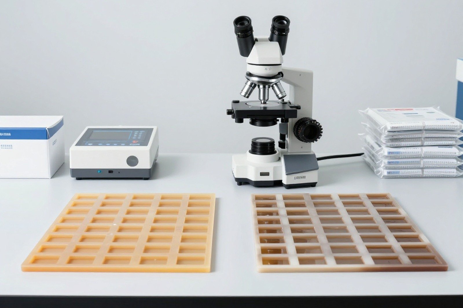
A familiar situation: the factory sends the same batch of samples to two testing laboratories, and receives two different conclusions. One laboratory said the solder joint was good, the other said the void exceeded the limit. Before concluding that either laboratory is wrong, it is important to understand that most of this difference comes from method, not from capability.
This article reviews six common sources of variation, how to identify them, and how to synchronize results between two laboratories.
1. Why can the same sample give different results?
Cross section is a plane sampling method. The results depend on where the plane is located, the depth of observation, how it is measured and how it is interpreted. All four can vary between two laboratories without either of them doing anything wrong.
2. Six common sources of difference
| Source of difference | Influence on results | How to recognize |
|---|---|---|
| Cutting position | Cutting through the centre of the ball row differs from cutting off-centre, giving a different shape and size | Compare the cutting location diagram recorded in the report |
| Cutting direction | Perpendicular cutting versus oblique cutting gives different sizes and shapes | Compare cutting direction with component layout |
| Grinding depth | Deep grinding can erase the intermetallic layer or reach another layer | Compare the details observed between the two sets of images |
| Measurement method | Measuring with a ruler on the photo is different from measuring with software, the errors are different | Check the scale and measuring tools stated in the report |
| Reference-point calculation | Same data but different reference points, different percentage results | Check the reference-point definition in the methods section |
| Interpretation of criteria | The same image can be read as pass or fail | Compare applicable standards and quality levels |
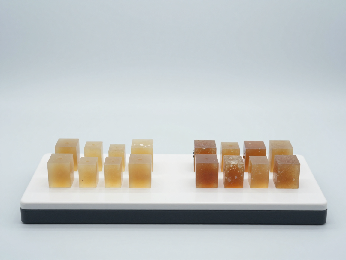
3. Location and cutting direction
This is the largest and least noticed source of variation. With BGA components, the cross section passing through the center of the row of balls will give a symmetrical ball shape; An off-centre cross section will show a distorted shape, and any measurement will be skewed with it.
For through-hole boards, cutting along the hole axis shows the entire length of the plating; Cutting at an angle will cut the plating into an ellipse and make the measured thickness inaccurate.
Principle: The report must clearly state the cutting location and direction, with a diagram. Without these two pieces of information, it is impossible to compare the two results.
4. Grinding depth and thin-layer condition
The intermetallic layer and thin plating layer can be gradually erased by grinding. Two laboratories grinding to different depths will see two different pictures of the same solder joint: one side still shows the intermetallic strip, one side has lost it.
How to check: request a report clearly stating which grinding steps were used and to what depth, with photos of each step if possible. If one side reports loss of intermetallic layer, it is necessary to check whether it is the result of over-grinding or whether the solder joint genuinely lacks bonding.
5. Measurement method and reference plane
| Factor | The two laboratories may differ | How to synchronize |
|---|---|---|
| Measuring tool | Ruler on photo compared to photo measurement software | Unify tools and require scales in photos |
| Measurement point | Measure at the thickest point versus measure at a representative point | Define measurement points in writing |
| Reference-point calculation | Calculated from the pad surface versus from the solder thickness | Clearly state the reference points in the method section |
| Number of measurements | Single measurement versus repeated measurement and averaging | Specify the minimum number of measurements |
| Rounding | Rounded to two decimals versus rounded to whole numbers | Specify the rounding convention |
6. Interpretation of criteria
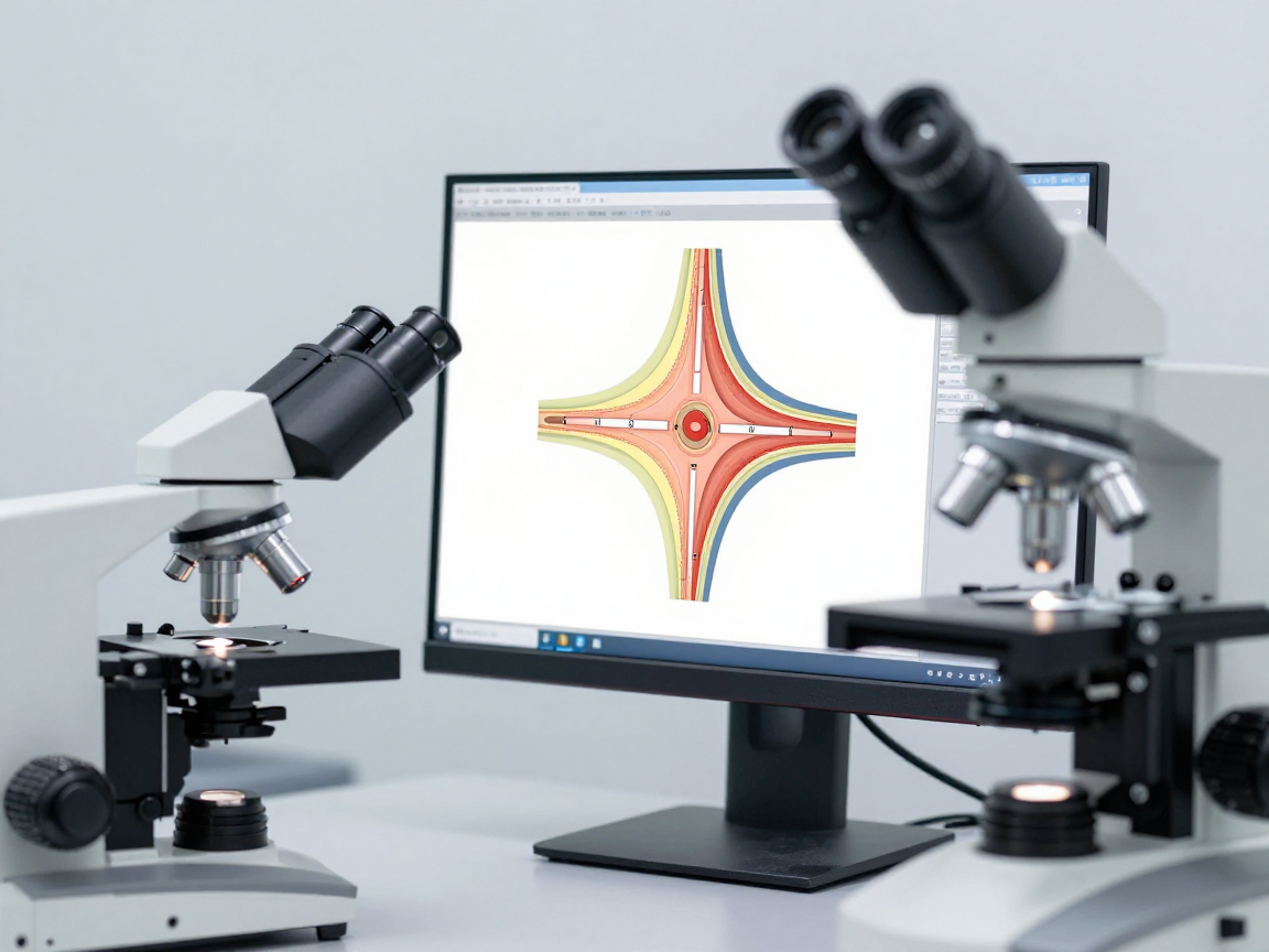
Even if two laboratories have the same data, the conclusions may still be different if the applied criteria are different. Common causes:
- Apply different standards to the same product type.
- Apply the same standards but different quality levels (product classes).
- One party applies internal criteria that are stricter than the reference standard.
- One party interprets the criteria according to the customer’s intended use.
This is not a technical error but a difference in scope of application. In a dispute, this is often the point that needs to be clarified first.
7. How two laboratories can align
- Written agreement: clearly state the cutting location, cutting direction, standards, quality levels, benchmarks and measuring tools.
- Use a zone map: divide the board into zones that correspond to the two laboratories so each one cuts at the same locations.
- Exchange photos before concluding: Compare images at the same magnification before comparing conclusions.
- Check suspicious marks: If one side sees defects that the other side does not see, request grinding again at a lighter step.
- Run periodic round-robin comparisons: With regular partner laboratories, periodic comparison of results helps reduce method differences.

8. When is a difference a sign of a real problem?
Not all differences are due to method. There are three worrying differences:
- Same cutting position, same depth, but different results: suggests the sample preparation process is problematic on one side.
- The results are unusually different between many samples: Suggests sample quality is not consistent, possibly due to production batch.
- One laboratory consistently gives dramatically different results: suggests that the party’s criteria or processes are not suitable for the purpose of the assessment.
9. Frequently asked questions
Which laboratory should we trust?
Don’t choose on gut feeling. You should ask both to provide photos, benchmarks and applicable criteria, then compare directly. In most cases you will find either an omission or a different criterion applied.
How can this be prevented from the start?
Agree in writing on the following elements: cutting location, cutting direction, standards, quality levels, benchmarks and measuring tools. This step takes little time but greatly reduces disputes.
What if one laboratory reports a much larger void?
Check the cutting position and observation depth first. Void varies markedly with the cutting plane so differences in cutting position can explain most of the difference.
Do we need a third party to arbitrate?
Should be done when the two laboratories cannot resolve it themselves and the value of the dispute is large. The third party needs all samples and method information from both sides.
Is any laboratory considered a reference?
There is no universal standard for all cases. It is essential that both parties have a verifiable process and apply the same agreed criteria.
10. Conclusion
When two laboratories give two different results, the most common cause is a difference in method — cutting location, grinding depth, datum or interpretation criteria — rather than professional error.
Four things to do: request a report that clearly states the cutting location and direction; Compare photos before comparing conclusions; agree on reference points and measuring tools in writing; and conclude that there is a capability problem only when both sides use the same method and still get different results.
References
- IPC-TM-650 Method 2.1.1 — Microsectioning.
- IPC-A-610 — Electronic Assembly Acceptance Criteria.
- J-STD-001 — Requirements for electrical soldering and electronic assembly.
- IPC-6012 — Technical requirements for rigid printed circuit boards.
Related articles
- Technical Cleanliness Testing per VDA 19.1: 7 Steps from Cleanliness Specification to Result
- 5 strange marks on the cross-section: distinguish real errors from phenomena due to sample preparation
- Measuring dimensions on cross-sectional images: how to set the ruler to minimize the error?
- Choose the cutting position and send the cross-section sample: one wrong step and you will lose the entire data set
- From cross-sectional image to root cause: 5 investigation steps
Talk to us
Disclaimer
This article is an interpretive content compiled by us; not legal advice. Enterprises need to compare relevant documents/standards verbatim before applying them to specific products.
See more: Copyright Policy & Disclaimer by ticforall.com.