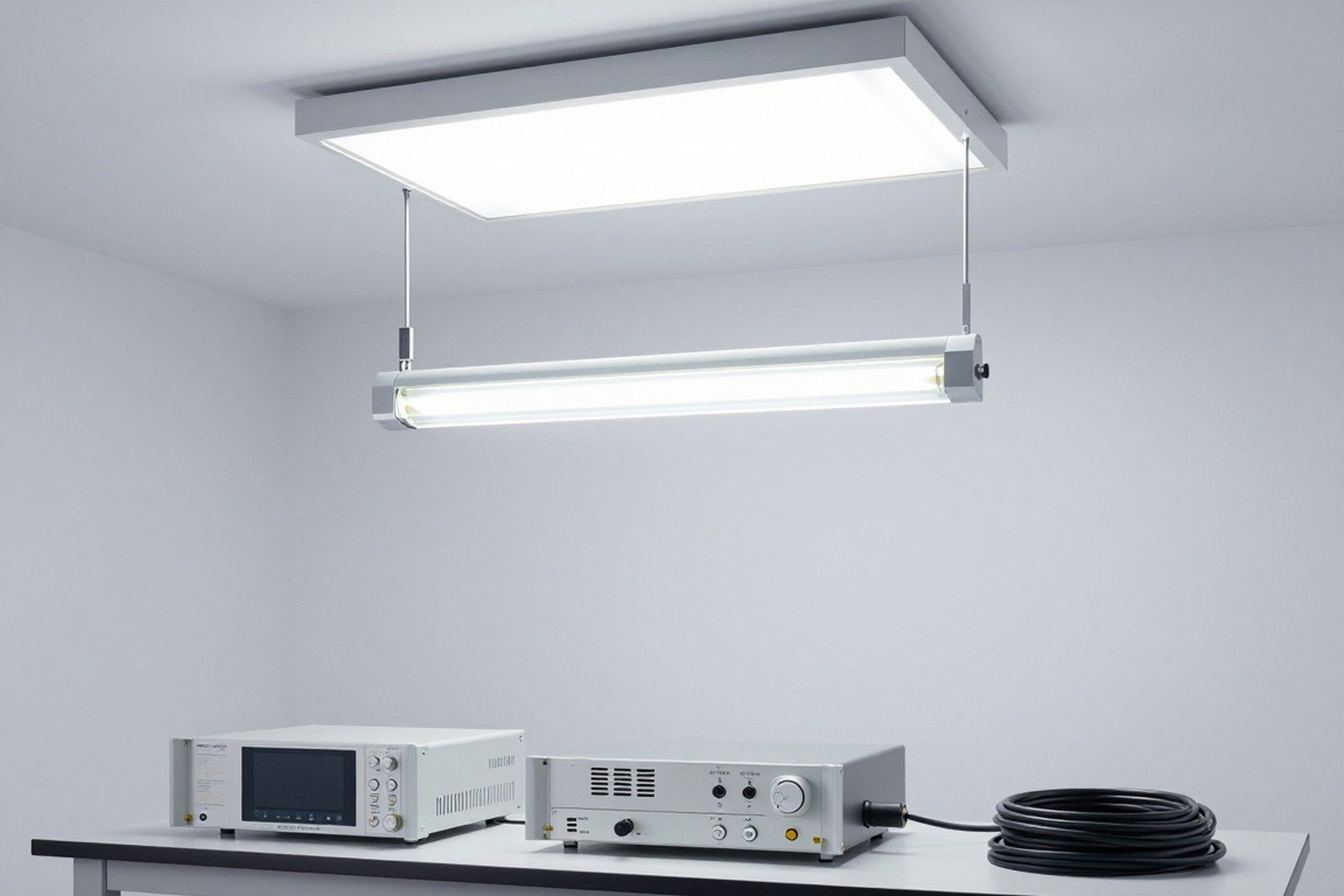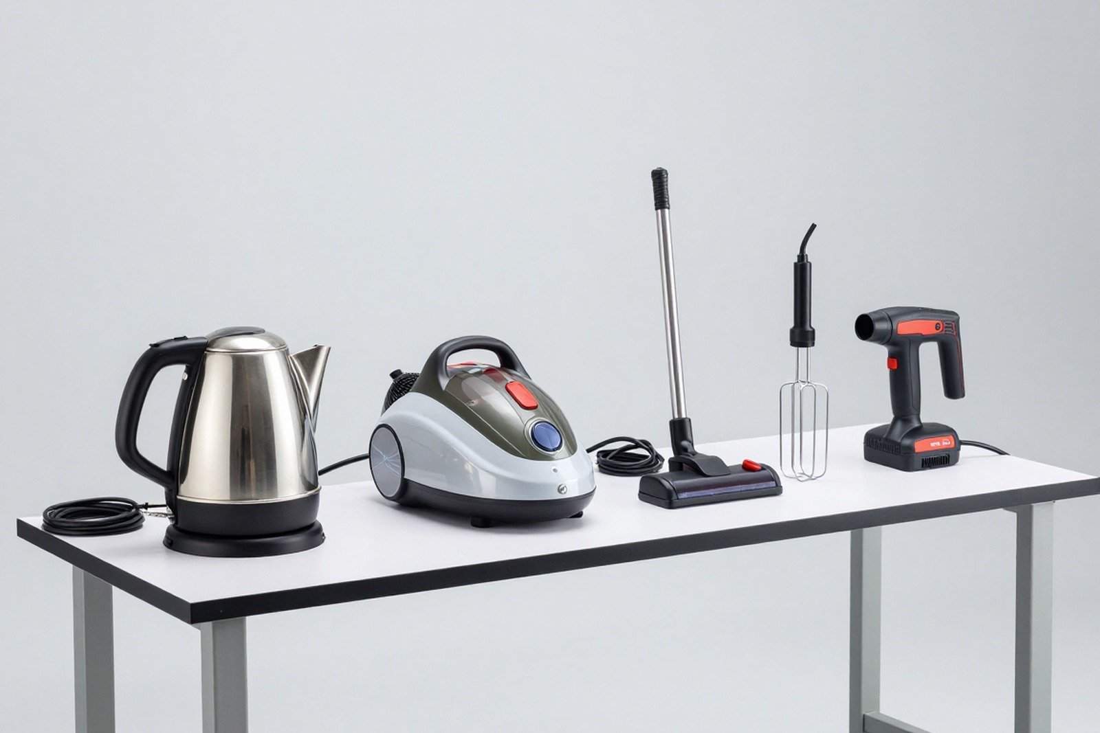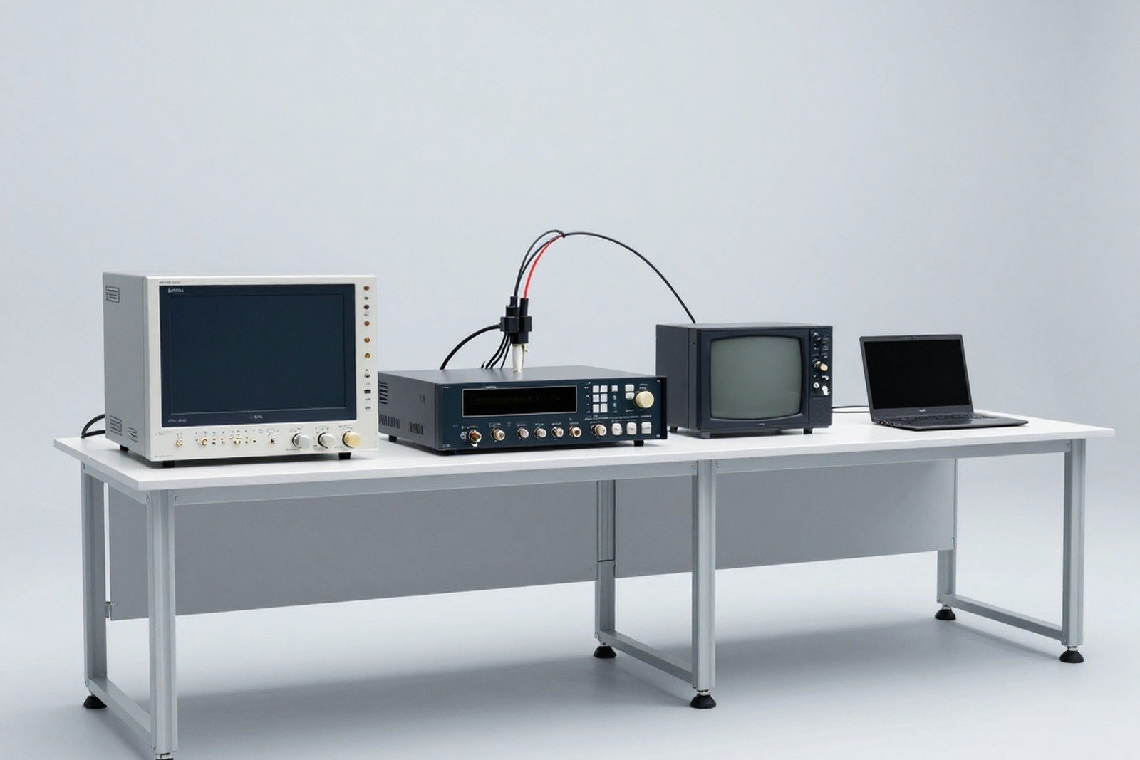
IEC 61000-4-2 Specifies an immunity test electrostatic discharge (ESD) — phenomenon that occurs when a person or electrically charged object touches the device. This is the most commonly performed immunity test, but also the one on which the results depend the most experimental arrangement: the same product, the same test level, two different ways of placing wires and coupling planes can give two opposite results.
1. How ESD builds up and how it causes damage
- Electricity source: People walking on carpets, plastic chairs, rubbing clothes, plastic bags, conveyor belts — can all accumulate electricity up to several kV, especially up to 15–35 kV when humidity is low.
- Launch path: through gaps, buttons, joints, metal casings, connection port contacts, key heads, screws.
- Consequences: Dead components (open oxide joints, punctured gates), but more common are temporary errors — crashes, resets, incorrect data, flashing screens, lost connections — errors that are difficult to find because they are difficult to reproduce.
2. How an ESD event is simulated
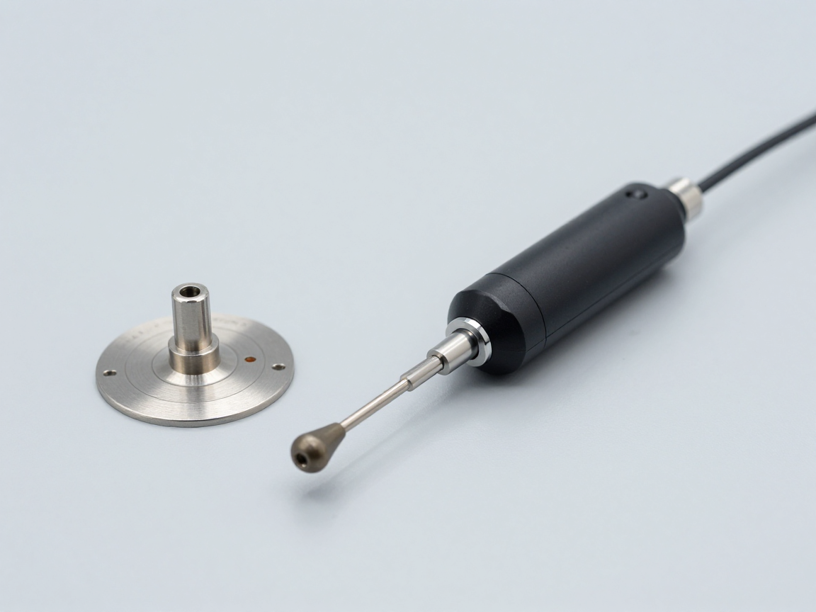
The ESD simulator consists of a simulation circuit 150 pF series 330 Ω (standard RC network) charged to the test voltage and then discharged through the contact or air-discharge electrode. The discharge current profile at 8 kV contact level must be within the specified window:
- Up time: about 0.7 – 1 ns.
- Top of first line: about 30 A (tolerance ± 30 %) at 8 kV.
- Value at 30 ns: about 16 A (± 30 %).
- Value at 60 ns: about 8 A (± 30 %).
This waveform is the reason “anti-ESD” cannot be just a protective device: 30 A peak per nanosecond requires a current drain extremely short and extremely direct about the ground plane.
3. Test levels
- Contact discharge: 2 kV — 4 kV — 6 kV — 8 kV; This is the preferred method because it repeats well.
- Air discharge: 2 kV — 4 kV — 8 kV — 15 kV; Used when the surface is not conductive and contact cannot be applied.
- X level Let product standards choose their own level, for example, medical, military, and telecommunications equipment have a higher level.
Principles of practice: Contact on all metal surfaces that is accessible to the user; spray air at the insulating surface (slots, plastic, stickers) and at joints.
4. Test set-up according to 61000-4-2
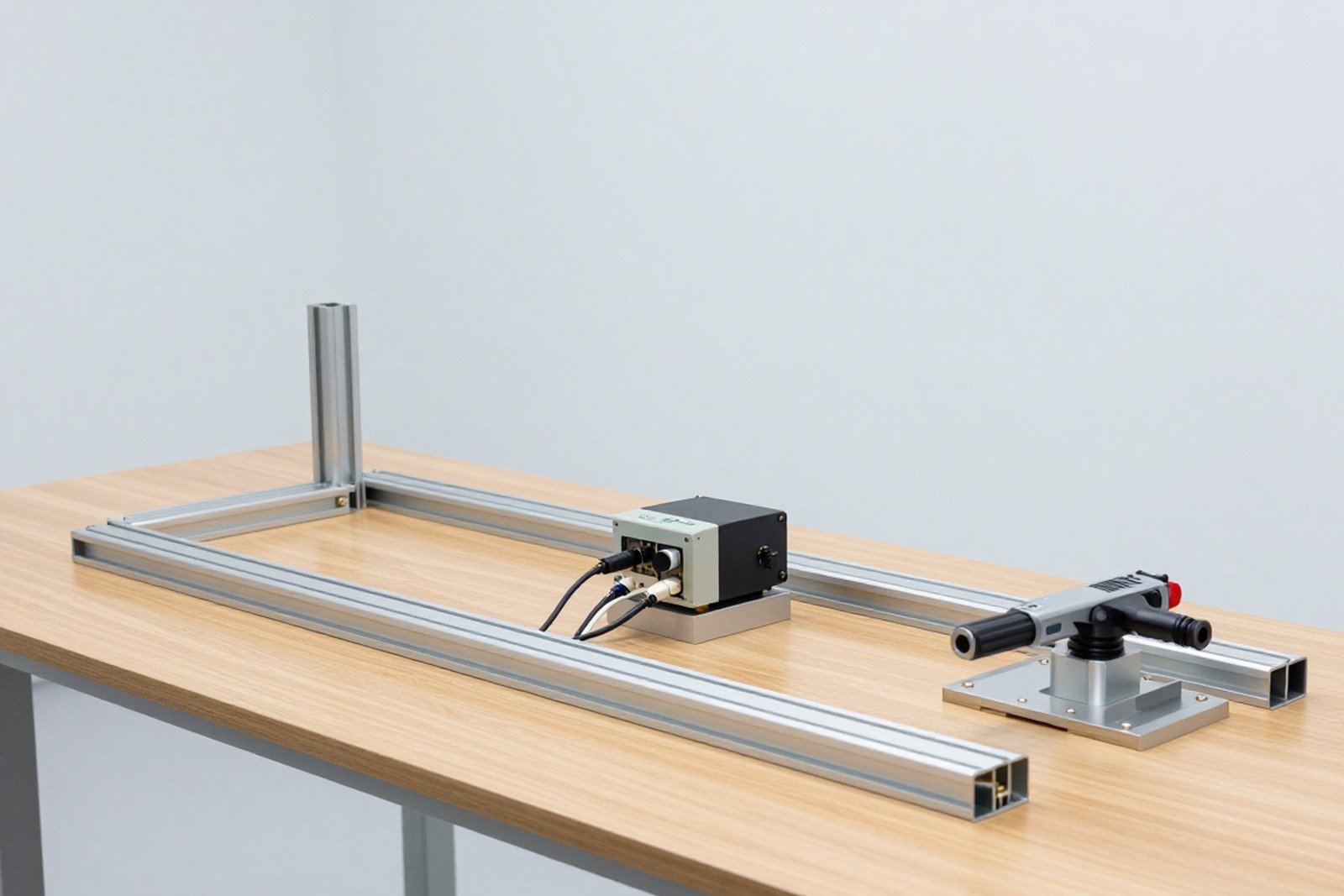
- Reference ground plane (GRP) made of metal, connected to protective ground, placed under the test table.
- Insulated table 0.8 m high, place the EUT with cables and auxiliary equipment on top.
- Horizontal graft plane (HCP) size 1.6 m × 0.8 m placed on the table, with a thin insulation layer between the HCP and EUT.
- Vertical graft plane (VCP) 0.5 m × 0.5 m located away from the EUT 0.1 m, the lower edge is 0.1 m away from the HCP.
- Discharge resistor 470 kΩ at both ends of the wire connecting HCP and VCP to GRP, to avoid electric charge and still retain coupling properties.
- Cables and connectors must be placed according to regulations regarding length and distance — incorrect placement is the number one cause of different results between two laboratories.
Indirect launch is performed on the HCP and VCP (applied at the edge and mid-plane) to simulate launching into a metal object near the device.
5. Number of discharges and how to run
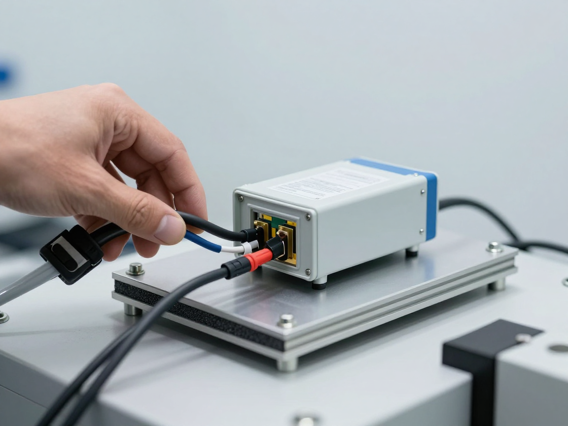
- Launch exposure: a minimum of 10 pulses per polarity at each selected test point.
- Air launch: minimum of 20 pulses (10 pulses per polarity) at each test point; In sensitive locations, it may be necessary to run additional consecutive pulses to find accumulated errors.
- Pulse interval: at least 1 second for the EUT to recover and for the insulation layer to not become electrically charged.
- Order of execution: run from low to high and record the exact error level — this is the most valuable information for design correction.
6. Calibration and uncertainty
- The ESD launcher must be calibrated as a flat line low impedance calibration target with a wide enough bandwidth, in accordance with the standards.
- In the new version, calibration requirements are added for both air-discharge electrode — the previous point was overlooked because the air spray waveform is highly dependent on distance and humidity.
- Test results must be accompanied by evaluation measurement uncertainty follow the general instructions of group 61000-4, and recheck the waveform before/after running to rule out instrument failure.
7. What is new in IEC 61000-4-2:2025?
- Additional requirements Calibrate the air-discharge electrode next to contact tip calibration.
- Added instructional appendix Select test point and number of pulses when launched into direct contact.
- Add appendix for wearable device and for some specific groups of equipment, there are separate test arrangements.
- Improved calibration requirements, uncertainty assessment, and clarification of post-installation testing steps.
8. Common mistakes in practice
- Set the VCP at the wrong distance (further than 0.1 m) reduces the coupling level, causing the device to “reach” artificially.
- No monitoring software — the device reset without anyone knowing, the report still recorded criterion A.
- Ignore indirect launch to HCP/VCP, while this is a common cause of errors for devices with long cables.
- Test at too high humidity cause insufficient air discharge to form — environmental conditions must be recorded in the report.
- Do not run the most sensitive operating mode (for example, USB + Wi-Fi + charging at the same time) so no error is detected.
9. Conclusion
IEC 61000-4-2 is more than just “8 kV shot”. The real value of the test lies in the correct layout, choosing enough test points, running the right number of pulses, closely monitoring the function and accurately recording the error level. By doing those five things, ESD results will no longer be “luck” but data that can be used to improve the design.
Related articles
- What is IEC 61000-4? Overview of immunity tests
- What is emission and immunity? EMC platform
- What is IEC 61000? Overview of electromagnetic compatibility standards
- Conformity assessment procedure 2026 for household appliances and ICT
Talk to us
Disclaimer
The article was compiled by us for interpretation; not legal advice. The above waveform and layout parameters are for illustration purposes only; You must refer to IEC 61000-4-2:2025 verbatim when planning the test. Copyright Policy & Disclaimer.