
TCVN 14538:2025 is a national standard on fire alarm transmission systems, drafted by the Police Department for Fire Prevention, Fighting and Rescue, proposed by the Ministry of Public Security and published by the Ministry of Science and Technology. Unlike standards that deal only with fire alarm equipment, this one sets requirements across an entire transmission chain: a transmitting device at the supervised premises, the transmission network, the receiving component and the continuously staffed receiving centre, down to the records kept after a signal has been passed to the fire service. This article outlines the scope, the architecture, the main requirement groups and the testing approach. Because the standard is copyrighted, the text below does not reproduce clause detail, data tables or annexes.
1. Background: why a standard for fire alarm transmission is needed
The legal framework for fire safety has just changed at both law and decree level. Law No. 55/2024/QH15 on Fire Prevention, Fighting and Rescue was passed by the 15th National Assembly on 29 November 2024 and took effect on 1 July 2025. Decree No. 105/2025/ND-CP dated 15 May 2025, detailing a number of articles and measures for implementing that law, also took effect on 1 July 2025.
In that setting, fire detection no longer stops at a sounder and a local panel. A signal has to travel through a chain of devices and services to a place where people are on duty continuously, be verified, and only then move to the fire service. Once transmission becomes a service, it needs technical benchmarks of its own: transmission time, reliability, availability, security and traceability.
TCVN 14538:2025 is a national standard and therefore applies voluntarily; it becomes mandatory only when referenced by a legal instrument, a technical regulation, a contract or a project dossier.
2. What the standard contains
The document consists of 7 clauses and 6 annexes. The first three annexes are informative and describe the structure of a transmission system, the structure of a transmission block and the way availability is understood. The last three are normative and cover access levels, testing of the transmitting device, and testing of the receiving component. Besides the clauses, the standard includes tables on fault reporting time, events to be logged and logical access levels, plus summary test schedules and a figure describing how alarms are handled at the receiving centre.
Clause 2 references four groups of documents: degrees of protection provided by enclosures (IP code); power supply equipment for fire detection and alarm systems; the environmental test series (cold, sinusoidal vibration, mounting of specimens for vibration and shock, hammer test, steady state damp heat, classification of environmental conditions); and two standards on electromagnetic immunity for components of fire and security alarm systems. The mix of national and international references shows that the testing part of TCVN 14538:2025 follows familiar environmental testing and EMC practice.
Because the standard is copyrighted, this article keeps to the outline; when preparing design, acceptance or test dossiers, users have to work from the official text and quote the correct number and year of publication.
3. System architecture and key concepts
The standard builds its own set of abbreviations to describe the transmission chain. Knowing these is the entry point for reading the clauses that follow.
| Abbreviation | Short meaning | Position in the transmission chain |
|---|---|---|
| FATS | Fire alarm transmission system | The whole system, comprising the transmission service network and the fire alarm receiving centre |
| FATSN | Fire alarm transmission service network | One or more transmission blocks supervised by a single service provider |
| FATB | Fire alarm transmission block | Transmitting device plus network, serving one supervised premises |
| SPT | Supervised premises transceiver | Sited at the premises, interfacing with the local fire detection and alarm system |
| FARC | Fire alarm receiving centre | Continuously staffed location that processes and verifies alarms before onward transmission |
| RCT | Receiving centre transceiver | Hardware or software at the centre, receiving signals from several transceivers |
| FAMS | Fire alarm management system | Handles, stores, retrieves and displays alarm data at the centre |
| FDAS | Fire detection and alarm system | The source of fire and fault status information |
| FATP | Fire alarm transmission path | The route an alarm or fault message takes, from the fire detection system to the management system |
| FATSP | Fire alarm transmission service provider | Responsible for designing, operating, managing and verifying performance of the service network |
Three further concept groups matter. The first concerns status and messages: genuine fire alarm, false fire alarm, indication, alarm filtering (deliberately holding a signal back for verification in order to limit false alarms) and fault messages. The second concerns the quality of a message: integrity, resistance to interference, correct reception and acknowledgement that it arrived. The third concerns performance and information security: system capacity, availability, fault reporting time, alongside security and anti-tamper requirements.
4. Requirements for the transmission service network
The requirements for the service network are organised by topic rather than by device. Read together, they fall into these groups:
- Configuration of the transmission block and how one block serves one or more fire detection systems on the same premises.
- Transmission paths and link types, including links shared with other applications or carried over third party network equipment, together with capacity requirements and protection against denial of service attacks.
- Block performance, assessed against transmission time and fault reporting time, with any transmission exceeding the permitted time treated as a fault.
- Monitoring of connections and fault reporting, distinguishing a block fault from a fault in an individual path.
- Message integrity assurance and acknowledgement of transmission between the two ends.
- Alerts generated by the transmission block, including the case where the block still operates while one of its paths has failed.
- Availability of the path, the block and the service network, with redundancy requirements, rules for deciding when a block is unavailable and recording of unavailability time.
- Security, split into anti-tamper protection and information security.
- Documentation that the service provider has to produce and maintain.
One governance point stands out: performance responsibility sits with the transmission service provider rather than with individual devices. The provider may delegate parts of the work through agreements, but remains accountable for the overall operation.
5. Requirements for the fire alarm transmitting device
For the device installed at the premises, requirements are set out in three layers: functional and operating, design, and additional requirements where the device is software controlled.
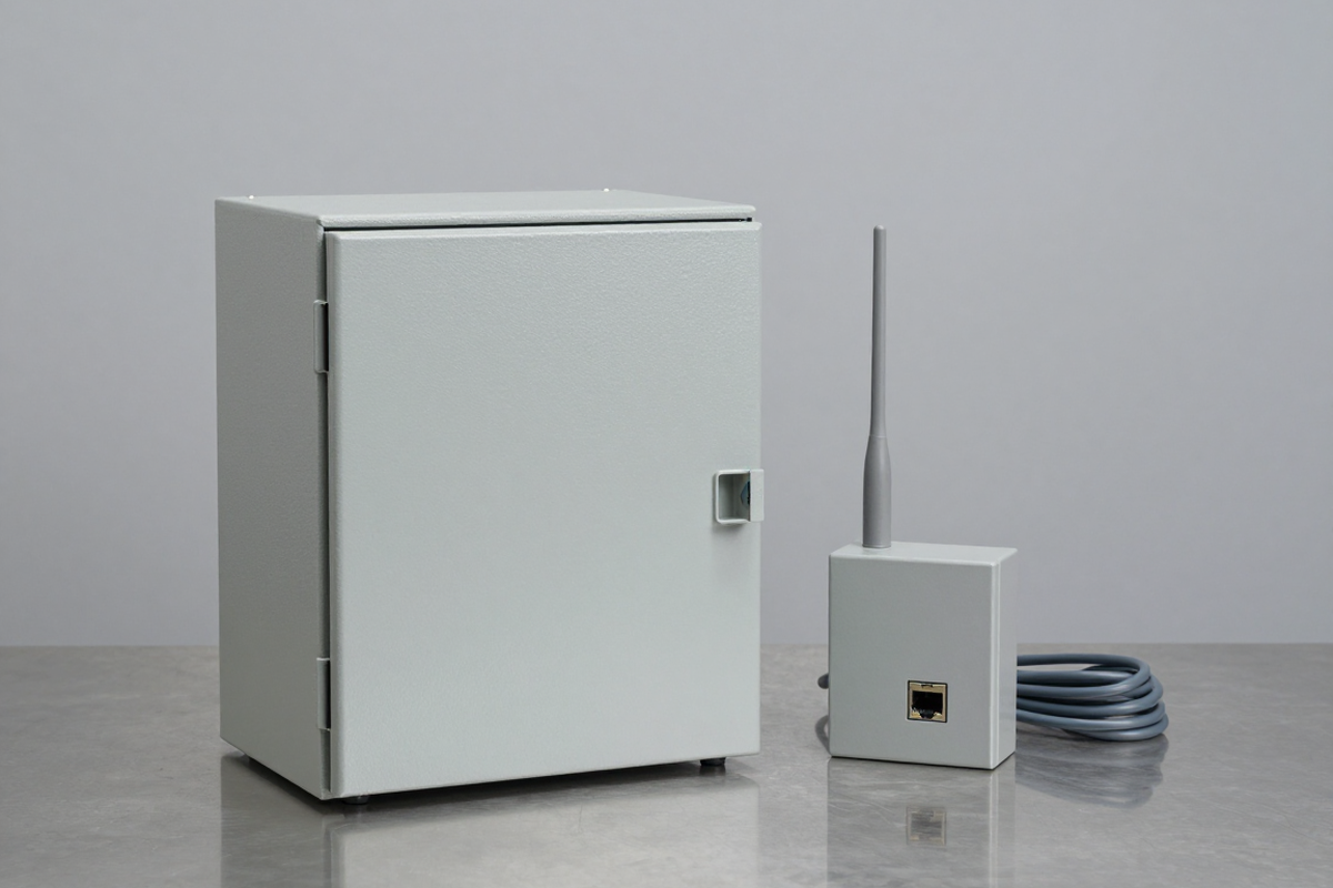
The functional layer covers signal processing; status and status indication; operating modes; the interface with the fire detection and alarm system; supervision of the network interface; alerts generated by the device; logical access; security; remote access; upload and download of software and firmware; parameter storage; and event logging. The design layer covers the manufacturer’s declaration, design documentation and technical files, mechanical design, electrical design, access to indicators and controls, and the indicators themselves.
For software-controlled devices the standard adds software documentation, software design, program supervision, storage of programs and data, and monitoring of memory content. The section closes with marking requirements.
6. Requirements for the receiving centre transceiver
The receiving component links the service network to the management system. It has to supervise the transmission blocks, receive and forward fire and fault messages, and monitor the status of those blocks. On access, the standard introduces access levels, key-based authorisation, individual accounts at higher levels, protection against code guessing, restrictions on default manufacturer keys and automatic logout of remote sessions.
On data, the receiving component needs event logging for traceability and fault handling, using non-volatile memory, with a minimum retention period, time resolution and synchronisation to international time; certain events must also be linked to a user identity. The standard also describes two possible operating modes: store and forward, or direct transmission. The section ends with denial of service protection, information security, anti-tamper protection, a backup receiving component, documentation and marking.
7. Requirements for the fire alarm receiving centre
The receiving centre is where people enter the process. The standard requires a procedure for handling alarms that removes false alarms before they reach the fire service, including alarm filtering. The management system at the centre has to accept status information, organise processing and storage, allow retrieval and display alarms.
Three further groups are often overlooked when dossiers are prepared. First, time synchronisation: every device that records a timestamp has to be synchronised to international time, and the system has to raise a fault alert when synchronisation is compromised. Second, storage: event records plus master data for each connected fire detection system, where master data must be updated when the supervised premises change. Third, power supply: the centre must be fed from two independent sources, main and backup, with changeover that does not interrupt operation, an indication of the source in use, and automatic return to the main source once restored.
8. Inspection and testing under the standard
Clause 7 splits testing into three blocks. For the transmission service network, the aim is to verify the performance of each transmission block under the real configuration and number of connected fire detection systems, including correct transmission of alarms and fault messages. The standard also requires performance testing at defined intervals, with adjustments where message volumes or transmission paths change, consolidated analysis of results, and availability records with a defined calculation.
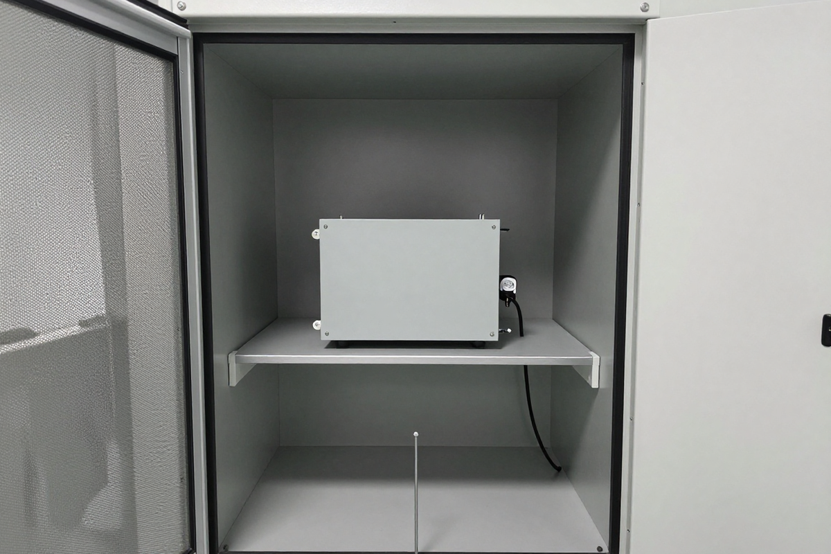
For the transmitting device, the standard sets out test environmental conditions, specimen preparation, a test programme covering functional tests under defined environmental conditions and environmental tests, and the number of specimens. For the receiving component, it sets out test conditions, installation, power supply, functional tests that demonstrate reception, forwarding, status indication and fault message generation, and checks of maximum fault reporting time for each path and every network interface used. The detailed schedules sit in the two normative annexes.
Because environmental and electromagnetic immunity testing is a large block of work, choosing the testing body often decides the dossier timeline. In practice, checking that the scope of accreditation covers the relevant tests matters more than the name of the laboratory.
9. What businesses and organisations should prepare
For manufacturers of transmitting devices, the task is to compare each group of functional, design, software, logging, security and marking requirements against the product, prepare design documentation and the manufacturer’s declaration, and plan environmental and immunity testing. For transmission service providers, the focus is availability records, redundancy arrangements, monitoring and fault reporting procedures, and a periodic testing plan with retained results.
For investors, building managers and industrial park operators, the focus is to bring these requirements into the design and acceptance dossiers for fire detection and alarm systems, and to compare them with the technical regulation on fire safety for buildings and structures when compiling dossiers. For testing laboratories and conformity assessment bodies, the task is to review whether their scope of accreditation covers the relevant tests before accepting designation or samples.
One procedural point is easily missed: the standard is copyrighted, so users need an official copy to cite in dossiers and contracts.
10. Frequently asked questions
Is TCVN 14538:2025 mandatory?
It is a national standard, so it applies voluntarily. It becomes mandatory only when referenced by a legal instrument, a technical regulation, a contract or a project dossier.
Does it replace standards on fire alarm equipment?
No. It addresses the transmission layer, covering the transmitting device, the service network, the receiving component and the receiving centre, so it adds requirements rather than replacing standards on fire detection and alarm systems and equipment.
Who needs to follow this standard?
Manufacturers of transmitting devices, fire alarm transmission service providers, receiving centres, designers and acceptance teams for fire detection and alarm systems, and testing and conformity assessment bodies.
How often must performance be tested?
The standard requires periodic performance testing with adjustments according to traffic and path conditions. The specific intervals and time limits are in the standard; this article does not reproduce the figures.
What is needed to test against this standard?
An official copy of the standard, a clear decision on which blocks apply, a testing body whose scope of accreditation covers the relevant environmental and immunity tests, and specimens prepared according to the specified test programme.
11. Related reading
- Choosing a testing laboratory for Vietnam compliance
- Designation of conformity assessment bodies under Decree 37/2026/ND-CP
- Dry heat testing under IEC 60068-2-2 and how tests are arranged
- Is 85/85 enough of a conclusion: limits of the hot damp test
- What emission and immunity mean: an EMC foundation for reading standards
12. References
- TCVN 14538:2025, Fire protection – Fire alarm transmission system, drafted by the Police Department for Fire Prevention, Fighting and Rescue, proposed by the Ministry of Public Security, appraised by the National Committee for Standards, Metrology and Quality, published by the Ministry of Science and Technology. The official text is available through national standards distribution channels.
- Law No. 55/2024/QH15 dated 29 November 2024 on Fire Prevention, Fighting and Rescue, effective from 1 July 2025.
- Decree No. 105/2025/ND-CP dated 15 May 2025 detailing a number of articles and measures for implementing the Law on Fire Prevention, Fighting and Rescue, effective from 1 July 2025.
- The standards referenced in Clause 2 of TCVN 14538:2025, covering degrees of protection provided by enclosures, power supply equipment for fire detection and alarm systems, environmental testing and electromagnetic immunity.
13. Contact
Manufacturers of fire alarm transmitting devices, transmission service providers and investors preparing design or acceptance dossiers for fire detection and alarm systems can send a request through the form below to discuss test scope and documentation.
This article is intended to share knowledge and does not replace the standard or technical and legal advice for a specific case. TCVN 14538:2025 is protected by copyright; this article summarises it only at a general level and does not reproduce clause detail, data tables or annexes. When applying it, use the official text together with the legal instruments in force.