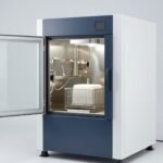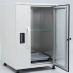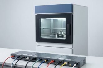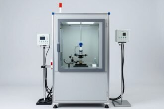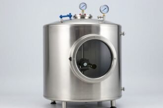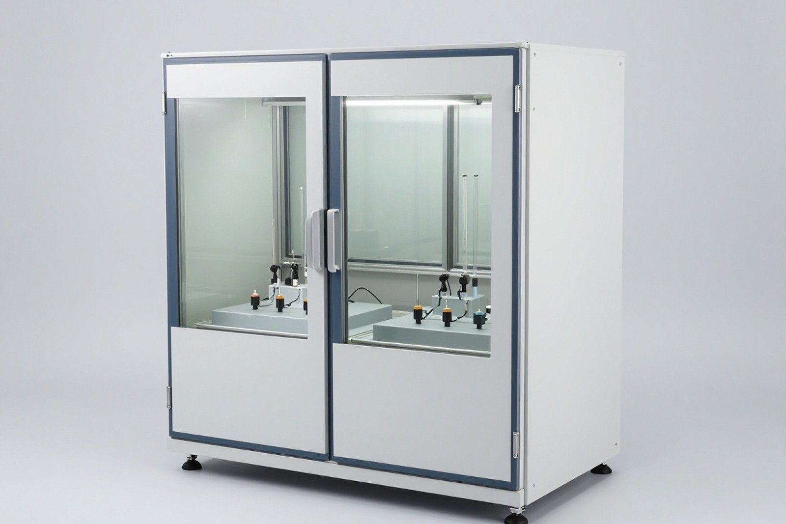
A common technical error in temperature testing: reading the temperature on the chamber screen, concluding that the sample has been subjected to the correct conditions, while the actual temperature of the sample is still on track to the required level — or has exceeded the required level due to the device self-heating when energized.
This article presents the principles of temperature measurement on samples in a loaded chamber, according to the guidance of IEC 60068-3-7, along with the points that must be recorded.
1. Why is chamber temperature not sample temperature?
Three reasons:
- Thermal inertia of the sample: Massive samples need time for the internal temperature to reach the ambient level. The chamber can reach level in just a few minutes while the sample takes tens of minutes or longer.
- Self-heating: The device being powered generates heat, creating a difference between the sample temperature and the chamber temperature.
- Local difference: In a large chamber, the temperature is not uniform; The same chamber can have colder and hotter locations.
Corollary: any conclusion about “the sample was subjected to condition X for time T” requires temperature data on the sample, not data set to the temperature of the chamber.
2. What does IEC 60068-3-7 instruct?
This part of the standard provides guidance on measuring temperature in a loaded temperature chamber — that is, when the chamber contains a test sample or simulated load. Core content related to:
- How to arrange temperature measurements to accurately reflect the conditions to which the sample is subjected.
- Effect of load (sample) on temperature distribution in the chamber.
- Principle for determining when the sample reaches the required temperature condition.
In other words: 60068-3-7 is a document so that temperature testing does not become “environmental measurement, sample conclusion”.
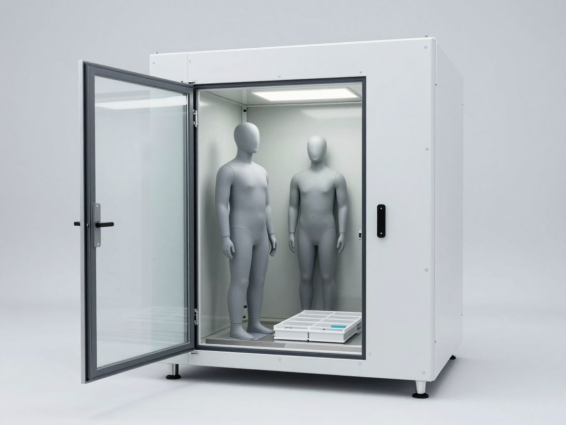
3. Principle of placing the temperature sensor on the sample
| Principle | How to do it | Why? |
|---|---|---|
| Place in a representative position | Choose a characteristic thermal point: near a heat-generating component, at a block with a large mass, at a location that is slowest to reach temperature | The slowest point determines the time needed to reach equilibrium |
| Attach firmly to the sample | Fix the sensor, ensuring good thermal contact | A separate sensor or poor contact will measure the air temperature, not the sample |
| Isolated from chamber walls | Do not let the sensor or wires touch the walls of the chamber | Avoid measuring chamber surface temperature instead of sample temperature |
| Use multiple sensors as needed | At least one sensor at a representative point; Add sensors at suspicious points | Detection of thermal gradients in samples |
| Record location | Draw a map of the sensor location and keep it on file | Ensure results are reproducible |
4. Self-heating and simulated load
When the device is tested in the energized state, the actual temperature of the sample may be higher than the chamber temperature. Needs to be handled in one of two directions, depending on the goal:
- Compensation: Set the chamber temperature so that the temperature at a representative point on the sample reaches the required level. This method simulates the conditions of use but requires measurement on the sample.
- Try without power: Evaluate viability, eliminating the effects of self-heating.
For testing on inactive samples but needing to simulate heat load (for example, a cluster with many components), some test laboratories use it download simulation — the part has mass and heat distribution similar to the real sample. When using simulated loads, the characteristics of the load and the reason for use must be clearly stated, because the results do not evaluate the functionality of the real product.
| Sensor placement/load handling error | Consequences |
|---|---|
| The sensor is placed in the chamber atmosphere, not attached to the sample | Reporting that the sample meets the conditions when in reality they do not — the conclusion is too optimistic |
| The sensor is mounted in the position where it is most likely to reach heat | The holding time is not enough for other areas of the sample |
| The sensor touches the wall of the chamber or metal tray | Measure device surface temperature, not sample |
| Self-heating is not included | The sample is subjected to temperatures higher than required, which may cause damage under improper conditions |
| No sensor location recorded | The results cannot be reproduced in the next attempt |
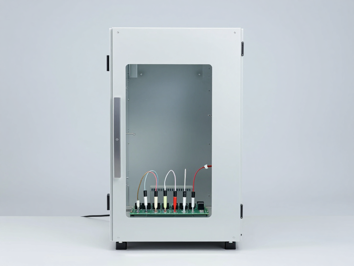
5. Determine maintenance time
The holding time must be sufficient for the sample to reach thermal equilibrium, not just for the chamber to reach set temperature. How to determine reality:
- Place the sensor at representative point(s) on the sample.
- Monitor sample temperature throughout the thermal transfer process.
- Determine when the sample temperature stabilizes within the allowable range.
- Start calculating maintenance time from that point (or as specified by the request).
- Record the entire temperature curve as evidence.
With large samples or multi-metal clusters, the time difference can be large. This is also the basis for selecting equipment and planning time for the testing room.
6. Documents to record
| Section | Content |
|---|---|
| Sensor location diagram | Location on sample, number of sensors, sensor type |
| Temperature data over time | Chamber temperature and sample temperature, recording frequency |
| Load characteristics | Power supply status, capacity, simulated load if available |
| Confirm chamber capacity | Results confirm temperature uniformity, with and without load |
| Maintenance time | How to determine, start and end time |
7. Common errors
- Record only the chamber’s set temperature In the report, there is no sample temperature data.
- Do not confirm chamber capacity under load, leading to unreliable temperature uniformity.
- Place the sensor in a convenient location instead of representative positions.
- Ignore spontaneous heating with active equipment.
- The sensor type and mounting method are not recorded. reduces ability to respond.
- Use the same measurement point for multiple samples while the samples are in different positions in the chamber.
8. Frequently asked questions
Is it mandatory to measure the temperature on the sample?
To draw firm conclusions about the conditions to which the sample is subjected, this data is needed. With small samples and low thermal mass, the difference may be small; but with large samples or powered equipment, omitting this measurement often leads to erroneous conclusions.
How many sensors is enough?
Minimum one sensor at representative point. Sensors should be added at points where thermal gradients are suspected or at main heat-generating components.
How to prove that the sample has reached thermal equilibrium?
Monitor temperature at representative point; When the temperature changes within the allowable range within a specified period of time, the sample is considered to have reached thermal equilibrium.
Can simulated loads be used instead of real samples?
Only for chamber capacity validation purposes or when real samples cannot be used. Results with simulated loads do not replace test results on real products.
How to handle sample temperature exceeding the required level?
Record the phenomenon, determine the cause (self-heating, chamber control error, mounting error), and evaluate the impact on the validity of the test. If the condition is false, the test must be repeated.
Where should I start if the test room does not have a measurement procedure?
From confirming the capacity of the loaded chamber, then building a process for placing sensors, recording data and determining retention time according to the characteristics of each type of sample.
9. Conclusion
Measuring sample temperature is the step that turns a temperature test from an “equipment operation” into a “technical proof”. Chamber temperature is the input condition; The sample temperature is the condition to which the product is actually subjected.
Three things to do: place the sensor at a representative point and record the position; saves temperature data over time for both chamber and sample; and include self-heating when testing electrically powered equipment.
References
- IEC 60068-3-7 — Guidance for measurements in loaded temperature chambers.
- IEC 60068-3-5 and 60068-3-6 — Validation of temperature chamber and heat-humidity chamber capabilities.
- IEC 60068-3-11 — Uncertainty of climatic conditions in the test chamber.
- IEC 60068-2-1, 2-2, 2-14 — Temperature tests.
- ISO/IEC 17025 — General requirements for testing and calibration laboratory competence.
Related articles
- Self-heating of the device: how to determine the appropriate chamber temperature
- Test A (Cold): cold test according to IEC 60068-2-1, how are Ab and Ae different?
- Moisture condensation when the sample leaves the cold chamber: causes and ways to control
- Pass/Fail Criteria After Environmental Testing and Interim Functional Checks
Discuss further
Disclaimer
This article is an interpretive content compiled by us; not legal advice. Enterprises need to compare relevant documents/standards verbatim before applying them to specific products.
See more: Copyright Policy & Disclaimer by ticforall.com.