IEC/IEEE 62209-1528:2020 is the first edition of the international standard that specifies measurement procedures for the specific absorption rate (SAR) of handheld and body-worn devices, covering the frequency range from 4 MHz to 10 GHz. It was published jointly by IEC and IEEE under the dual logo agreement in October 2020, merging and replacing IEC 62209-1:2016, IEC 62209-2:2010, Amendment 1:2019 to Part 2 and IEEE Std 1528-2013. This article summarises the scope, what changed compared with the previous standards, and the points to check when reading a SAR report or selecting a test laboratory.
1. What SAR is and why it is measured
SAR (specific absorption rate) is the power absorbed per unit mass of tissue, expressed in W/kg. Because SAR is not distributed uniformly in tissue, the quantity compared with exposure limits is the peak spatial-average SAR, that is the highest SAR value averaged over 10 g or 1 g of tissue shaped as a cube. The two limits commonly applied are 2,0 W/kg averaged over 10 g of tissue under ICNIRP and European rules, and 1,6 W/kg averaged over 1 g of tissue under the rules of the United States FCC.
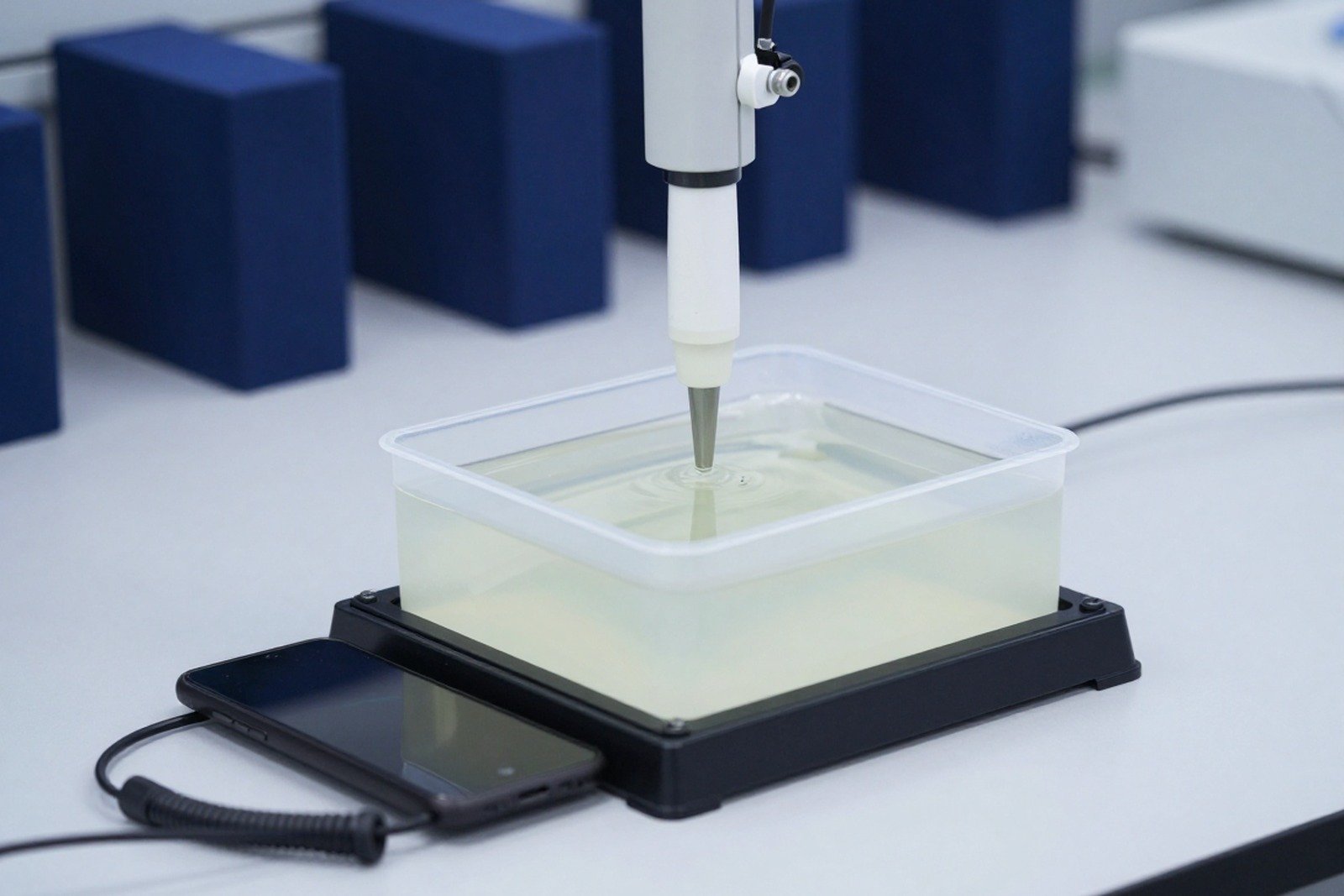
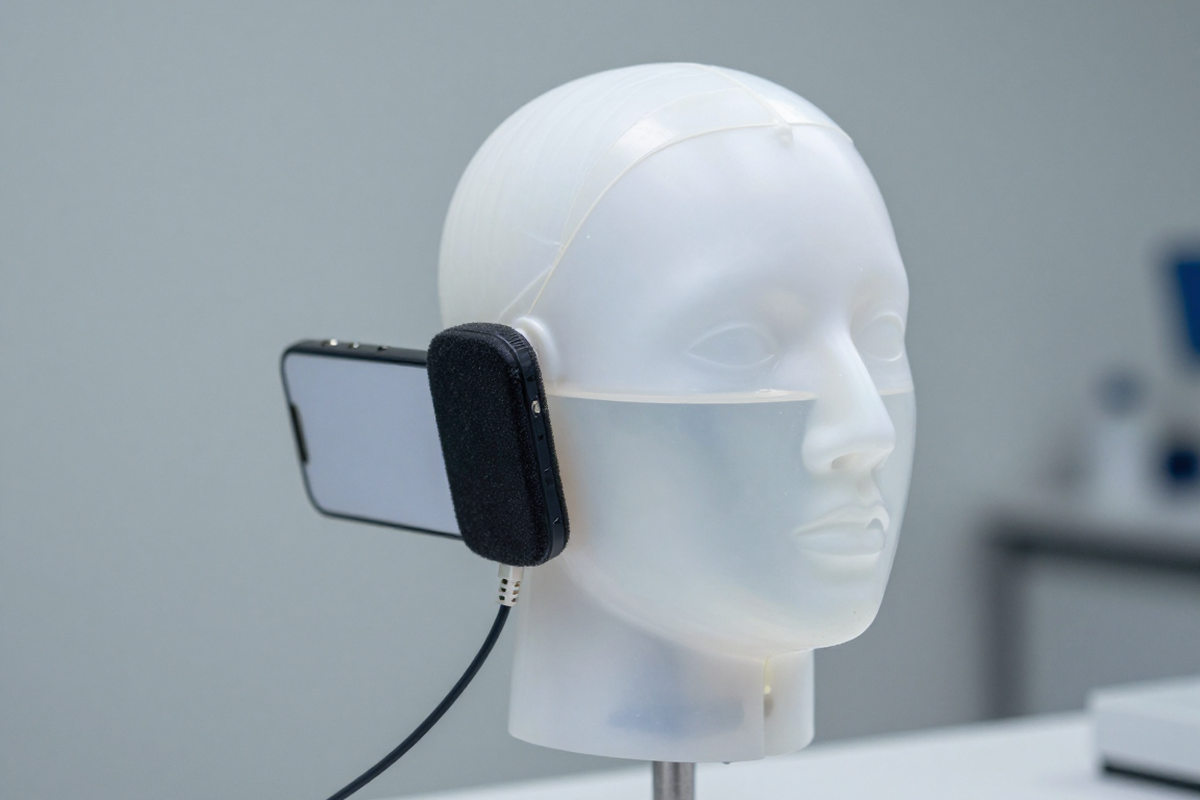
Measurement uses head and body models filled with a tissue-simulating liquid, a field probe for direct measurement, a three-axis scanning system and a device holder. Results depend on device position, operating mode, transmit power and the dielectric properties of the liquid, so the procedure must be described in enough detail to be repeatable. In EMC documentation the abbreviation SAR also stands for semi-anechoic room; the two meanings are unrelated.
2. What IEC/IEEE 62209-1528 replaces
The foreword states that this first edition cancels and replaces four documents: IEC 62209-1:2016, IEC 62209-2:2010, IEC 62209-2:2010/AMD1:2019 and IEEE Std 1528-2013. Merging Part 1, for head SAR of handheld devices, and Part 2, for body-worn devices, into one document removes the need to pick a standard by intended use, while specific procedures are still kept for individual device groups. The electronic edition includes the Fast SAR Wizard tool described in 7.9.2.2 and CAD files of the SAM phantom. IEC 62209-3:2019 for vector measurement-based systems in the range 600 MHz to 6 GHz remains in force and is referenced as a normative reference.
| Topic | Change compared with the earlier standards |
|---|---|
| Frequency range | Widened to 4 MHz at the bottom and 10 GHz at the top, instead of being split between two parts |
| Proximity sensors | New procedures to determine sensor triggering distances and coverage area |
| Phantoms and device holder | Application-specific phantoms allowed; holder material and mounting specified |
| Fast SAR and test reduction | New fast SAR procedures and test reduction rules with statistical support |
| LTE assessment | Dedicated assessment procedure for LTE added |
| System verification | Validation clause revised, including validation antennas |
| SAR assessment procedure | Measurement procedure revised; time-period averaged SAR added |
| Uncertainty | Uncertainty analysis revised throughout |
3. Scope: frequency range, distance and device types
The standard specifies protocols and test procedures for reproducible and repeatable measurement of the peak spatial-average SAR induced in a simplified head and body model by radio frequency transmitting devices. It applies to handheld and body-worn devices with one or more antennas or transmitters, operated with their radiating structures at distances up to 200 mm from the head or body, over the frequency range from 4 MHz to 10 GHz.
Device categories include mobile telephones, cordless microphones, radio transmitters in personal, desktop and laptop computers, multiband devices with one or more antennas, and push-to-talk devices. The standard can also be applied to wireless power transfer devices operating above 4 MHz; implanted medical devices are excluded. Between 6 GHz and 10 GHz the SAR standard overlaps with joint IEC/IEEE projects on power density, and the joint working group left the choice of metric to the assessor for each case.
4. Structure of the standard and its annexes
The document starts with a quick start guide and an evaluation plan checklist in Clause 5, followed by measurement system requirements in Clause 6, the SAR assessment protocol in Clause 7, uncertainty estimation in Clause 8 and reporting in Clause 9. The annexes are split into normative and informative groups, and a test report should be checked against the annexes it invokes.
The normative annexes cover system verification (Annex A), validation antennas (Annex D), calibration and characterisation of dosimetric probes (Annex E), phantom specifications (Annex G), application-specific phantoms (Annex K), fast compliance evaluation with a curved-corner flat phantom (Annex L) and uncertainty analysis aimed at the makers of measurement systems and at calibration laboratories (Annex O). The informative annexes cover the basis for test reduction and the uncertainty of fast SAR methods (Annexes B and C), tissue-equivalent liquid recipes and dielectric property measurement (Annexes F and H), hand effects and the skin enhancement factor (Annexes I and J), and wired hands-free headset testing plus guidance on applying the head SAR procedures (Annexes M and N).
5. Measurement system and tissue-equivalent medium
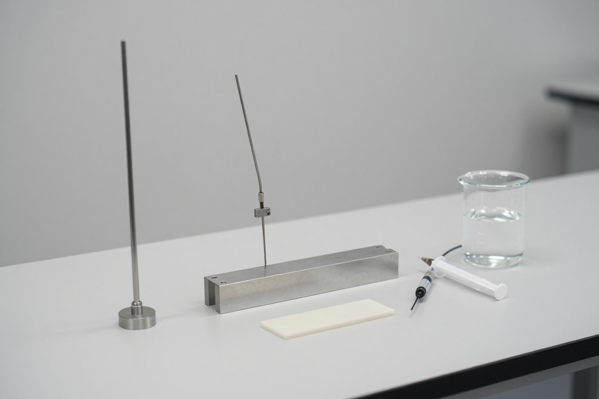
Clause 6 defines the minimum configuration of a full SAR measurement system: a phantom filled with tissue-equivalent medium, readout electronics, a scanning system and a device holder. Two basic phantom types are used, the SAM phantom representing the human head and the flat phantom representing the body, and application-specific phantoms are permitted under Annex K, for example a wrist phantom. The device holder is made of low-permittivity, low-loss material with thin foam to avoid changing device performance.
For the flat phantom the recommended medium depth is at least 15 cm with a tolerance of 0,5 cm to limit reflections; with a thinner layer the reflection effect on the result must be shown to be below 1 % by numerical simulation, and between 1 % and 3 % the corresponding uncertainty must be added. The liquid must meet the target values for the real part of the relative permittivity, conductivity and density given in Table 2 of the standard for the frequency and tissue type in question.
The values used in SAR calculations are the measured properties of the liquid batch at the time of the test, not the target values in the table. Errors caused by cables, reflecting objects and equipment must be kept below 0,012 W/kg, corresponding to 3 % of 0,4 W/kg; where this cannot be achieved, ferrite beads, RF absorbers and other mitigation techniques must be applied and reported.
6. Device positions during measurement
Clause 7.2.4 defines how the device is positioned for each type of use, with a separate set-up procedure based on reference points and reference lines marked on the device. Devices used against the ear have two positions, the cheek position and the tilt position, the tilt position being established by rotating the device 15 degrees away from the cheek around the contact point.
Other position groups cover front-of-face devices such as two-way radios and camera devices, handheld devices not used at the head or torso, limb-worn devices, clothing-integrated devices, desktop devices and devices with an alternative form factor. Body-worn devices are tested at the separation distances implied by their accessories, such as belt clips, wrist straps or lanyards. Any deviation from the standard set-up, including mounting and alignment adjustments, must be documented in the measurement report.
7. The full SAR measurement procedure
The procedure starts with medium preparation, a system check and determination of the device operating mode, after which the device is positioned for the test. Measurement consists of a coarse area scan to locate the region of highest SAR, followed by a fine three-dimensional zoom scan at that location with a smaller step size to compute the peak spatial-average SAR over 10 g or 1 g of tissue. Before each series of measurements the system must be checked according to Annex A, on the same system and in the same frequency range used for the assessment.
Post-processing in Clause 7.5 covers interpolation between measurement points beyond the probe boundary, extrapolation to the phantom surface, definition of the averaging volume and search for local maxima. Clause 7.4.3 requires the power drift during measurement to be evaluated and the results to be corrected when the drift exceeds the permitted value. For devices with multiple antennas or transmitters, Clause 7.4.4 specifies how each transmitting configuration is measured and how results are combined.
8. Multiple transmitters, simultaneous transmission and proximity sensors
Modern devices may transmit simultaneously using several technologies such as GSM, WCDMA, LTE, 5G NR, Wi-Fi and Bluetooth. For these cases the standard provides an exclusion power threshold: a transmitter needs to be measured only when its output power exceeds the product of the SAR limit and the averaging mass. For example a limit of 2,0 W/kg with a 10 g mass gives a threshold of 20 mW, and a limit of 1,6 W/kg with a 1 g mass gives 1,6 mW.
Clause 7.6 covers time-period averaged SAR for devices whose instantaneous power varies but which maintain a defined average power over a time period; this allows compliance to be demonstrated on average power rather than peak power, with its own uncertainty requirements. Clause 7.7 addresses devices with proximity sensors that reduce power when held against the body: determining the sensor triggering distance, determining the sensor coverage area, and the corresponding SAR measurement procedure. Testing must verify both the full power state and the reduced power state, with the sensor disabled and enabled, using manufacturer test software, conducted power measurement or radiated power measurement.
9. Reducing test time: fast SAR and test reduction
Clause 7.9 contains two groups of techniques. The first is fast SAR testing, which uses a system validated separately under Annex A.4 and evaluated for uncertainty under Annex C; some methods use a curved-corner flat phantom specified in Annex L. The second group is the test reduction rules based on device design characteristics, measured SAR levels in selected configurations and statistical analysis, with the supporting basis set out in Annex B.
When reading a report, check whether test reduction was applied, on what basis, and whether the configurations capable of the highest output power were actually measured. Test reduction does not mean that adverse configurations can be skipped.
10. Measurement uncertainty and permittivity correction
Clause 8 puts the uncertainty statement at the 95 % confidence level and caps the expanded uncertainty at 30 % of the peak spatial-average SAR over the 0,4 W/kg to 10 W/kg band. Under 0,4 W/kg the corresponding cap is 0,12 W/kg, which is 30 % of 0,4 W/kg. If a national rule tolerates a larger expanded uncertainty, the report has to state how far the achieved figure sits above the 30 % target and adjust the data accordingly.
Contributing parameters include probe and readout errors, the dielectric properties of the medium, probe and device positioning, coupling between the test device and the field probe, plus the parameters specific to fast SAR methods listed in Annex C. System check and system validation results must also be evaluated for uncertainty. Because a prepared liquid may deviate from the target complex permittivity, Clause 7.8 provides a SAR correction formula based on the measured real permittivity and conductivity, together with the uncertainty of the correction itself.
11. System check, probe calibration and validation antennas
Annex A defines two periodic checks. The system check uses a standard antenna radiating into a flat phantom with the recommended medium, measuring peak spatial-average SAR over 1 g and 10 g normalised to 1 W of input power; results must not deviate by more than 10 % from the numerical target values. System validation uses validation antennas to verify the complete measurement system. The check frequency has to stay inside the range where the calibration factors remain valid, and no further than 10 % or 100 MHz away from the mid-band frequency of the compliance test, taking the larger figure; beyond 6 GHz the permissible gap widens to 1 GHz.
Annex D lists the validation antennas: the standard dipole, the standard waveguide, the confined loop and meander dipole for frequencies below 150 MHz, and the orthogonal field source. The gap between antennas is set by dielectric spacers held to tight tolerances, at 15 mm from 150 MHz to 1 000 MHz, 10 mm above 1 000 MHz up to 6 000 MHz, and 5 mm beyond 6 000 MHz up to 10 GHz.
Annex E specifies the calibration and characterisation of dosimetric probes, covering linearity, sensitivity of individual dipole sensors, axial and hemispherical isotropy, lower detection limit, boundary effect and response time. Annex G specifies phantom characteristics, while Annex O gives guidance on uncertainty analysis to the makers of measurement systems and to calibration laboratories.
12. Reporting and how to review a SAR report
Clause 9 requires the measurement report to contain enough detail to allow the evaluation to be repeated and the results to be compared with the applicable limit. Content includes the device description and operating modes, test positions, measurement system parameters, system check and validation results, the measured dielectric properties of the medium, peak spatial-average SAR over 1 g and 10 g, measurement uncertainty and any corrections applied. For fast SAR methods the report must state how the post-processing algorithms differ from those used for full SAR testing.
When commissioning a test laboratory, verify three things: that the ISO/IEC 17025 scope of accreditation covers the 62209-1528 standard and the frequency range of the product, that the measurement system has phantoms suitable for the intended use positions such as head, body or limb, and that the report states the expanded uncertainty together with a conclusion against the specific limit of the target market. For export files, a SAR report under the 62209 and IEEE 1528 family is commonly requested alongside radio and electrical safety test results.
13. Related articles
- QCVN 117:2023/BTTTT: RF standard for mobile terminals
- QCVN 136:2025/BKHCN: 6 GHz Wi-Fi equipment regulation
- QCVN 55:2023/BTTTT: short range devices 9 kHz to 30 MHz
- QCVN 127:2021/BTTTT: standalone 5G UE requirements
- QCVN 129:2021/BTTTT: non-standalone 5G UE
- Circular 08/2021: radio frequency licence exemptions
14. References
- IEC/IEEE 62209-1528:2020, Measurement procedure for the assessment of specific absorption rate of human exposure to radio frequency fields from hand-held and body-mounted wireless communication devices, Part 1528: Human models, instrumentation, and procedures, frequency range 4 MHz to 10 GHz, edition 1.0 published October 2020, ISBN 978-2-8322-8533-6. Consult the IEC Webstore and IEEE Standards.
- IEC 62209-3:2019, same series, Part 3: Vector measurement-based systems, frequency range 600 MHz to 6 GHz.
- IEC 62209-1:2016, IEC 62209-2:2010, IEC 62209-2:2010/AMD1:2019 and IEEE Std 1528-2013 are the documents cancelled and replaced; ISO/IEC Guide 98-3:2008 is the GUM guidance on uncertainty of measurement.
- IEC and IEEE standards are copyright protected and the full text must be purchased from the publisher; this article summarises and cites the standard instead of reproducing it.
15. Contact
If your product needs to be checked against the scope of IEC/IEEE 62209-1528:2020, a SAR report prepared for an export market, or a test laboratory with a suitable scope of accreditation, please send the details using the form below.
Note: This article is published for general information about the standard and does not replace the full text of the standard or technical advice for a specific case. Before applying it, purchase and check the original IEC/IEEE 62209-1528:2020 including Annexes A to O, together with any amendments in force.