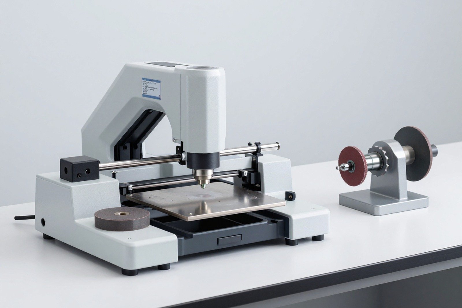
In the cross-section, the microscope is just the one recording the results. What determines whether the image shows structure or not lies in the four previous steps: cutting, molding, grinding and polishing. An incorrectly prepared sample can hide real defects, or create false defects that do not exist.
This article describes each step, the typical errors of each step, how to recognize a damaged sample and how to reduce it depending on the skill of the operator.
1. Sample preparation chain and principles throughout
- Cut — separate the area to be surveyed from the details.
- Casting — secure the pattern in the plastic mold and protect the cut edge.
- Grinding — bring the section to the correct plane to be examined.
- Polishing — removes scratches and surface deformation layers.
- Corrosion — increase structural contrast, use only when needed.
Cross-cutting principles: Each step must be processed enough to eliminate the influence of the previous step, but not processed so much that the part to be examined is lost.. Most sample preparation errors are violations of one of the two sides of this principle.
2. Sample cutting: control heat and cutting plane
| Factor | Need control | If you do it wrong |
|---|---|---|
| Cutting blade | Choose the type of abrasive suitable for the material | Grinding too hot, burning edges, deforming the plating layer |
| Cooling solution | Enough flow, right spray direction | The heat generated softens the base plastic and deforms the solder joint |
| Cutting speed | Slow for samples with small solder joints, faster for thick metal samples | The cut is beveled, small details are lost |
| Clamp direction | Perpendicular to the axis you want to survey | Measured thickness is larger than actual |
Signs of sample damage due to cutting: burned cutting edges, scratched metal layer along the blade direction, plastic plastic deformation. When seeing these signs, conclusions about thickness should be kept cautious.
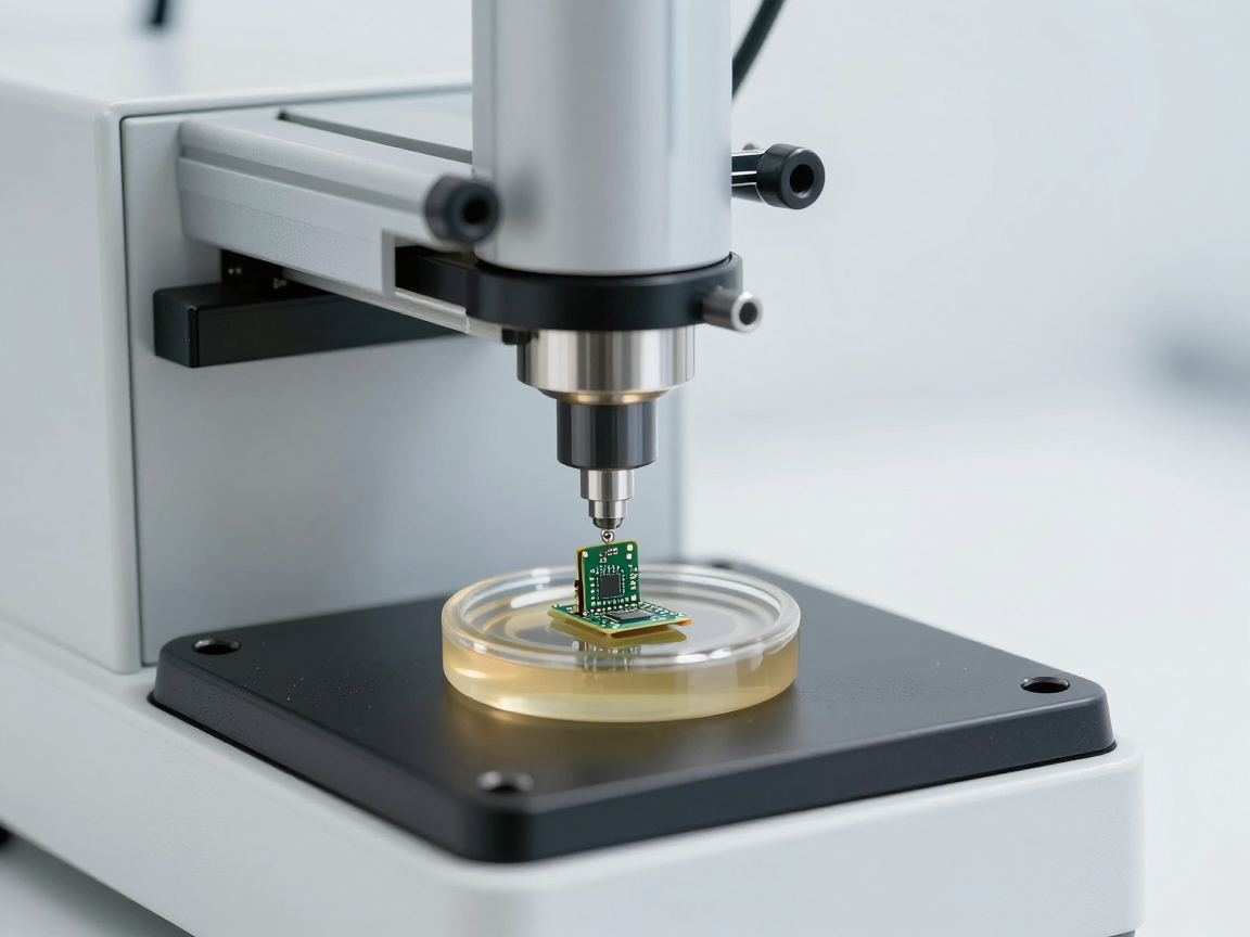
3. Molding the pattern: holds it in place and protects the edge
| Method | Characteristics | Fits |
|---|---|---|
| Hot molding (thermoplastic) | Quickly, the sample is pressed under conditions of heat and pressure | Metal samples, circuit boards, and heat-resistant parts are good |
| Cold molding (two-component resin) | No heating, longer setting time | Heat-sensitive samples: small solder joints, plastics, soft materials |
Three common errors in the molding step: plastic flows into the gaps between the parts, causing wrong edges of the sample; The sample moves during the setting process; and shrinking plastic creates a gap between the sample and the plastic — this gap when ground will attract impurities and create fake streaks in the image.
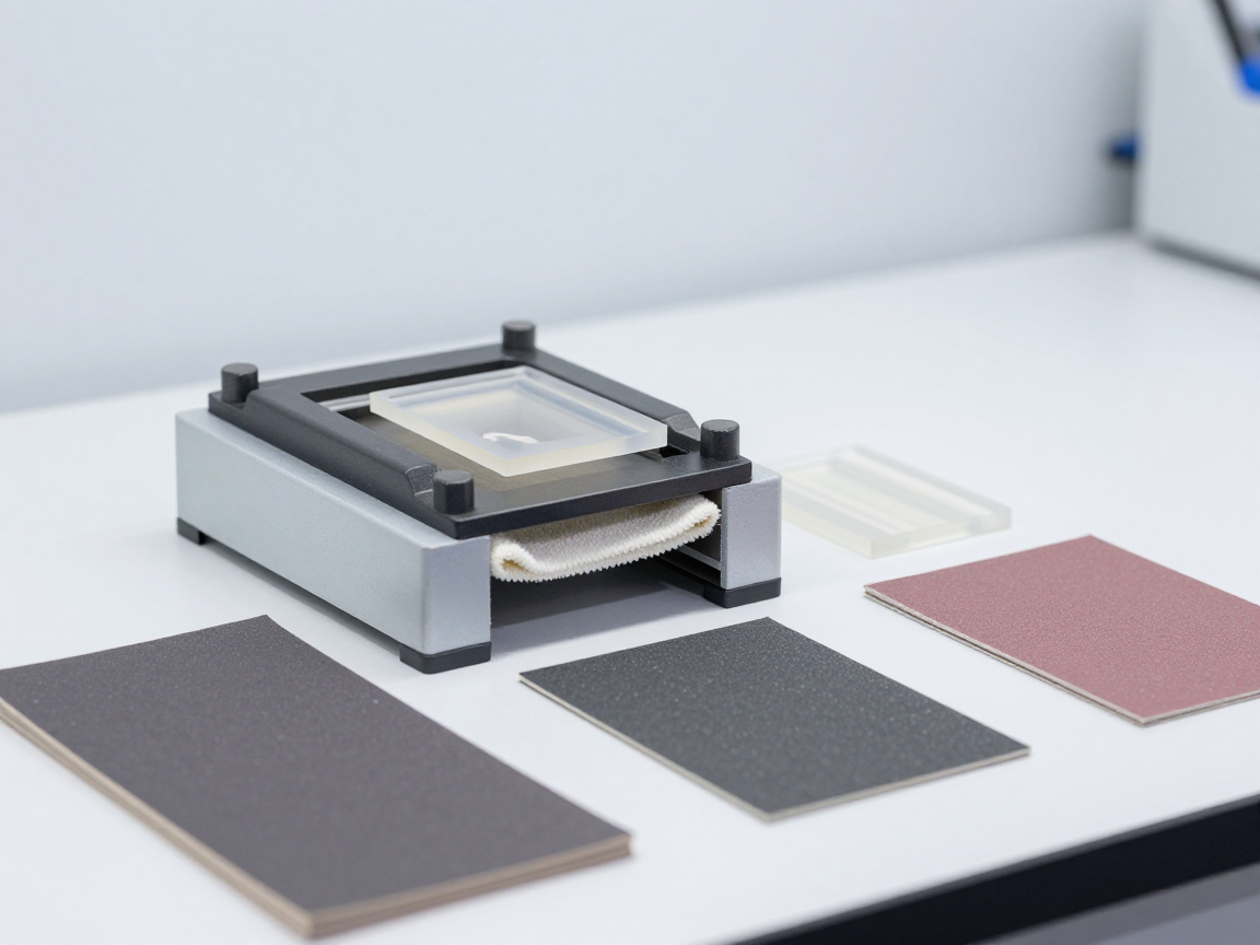
4. Grinding: downgrading the grain step by step
| Phase | Purpose | Signs of needing to move forward |
|---|---|---|
| Rough grinding | Flatten and approach the correct plane to be examined | The entire cross-section is flat, no cuts remain |
| Middle grinding | Type the large scratch from the previous step | Unidirectional scratches |
| Fine grinding | Kind of small scratches | The surface is evenly matte, no scratches can be seen at low magnification |
Two common mistakes: skipping a certain grain level (resulting in deep scratches remaining at the end) and grinding in a single direction for too long (resulting in an uneven surface, with one side beveled).
5. Polishing: processing the deformation layer
Grinding creates scratches, and polishing creates a thin layer of deformation on the surface. This layer can hide small details such as the intermetallic compound (IMC) layer or make the plating layer appear thicker than it actually is.
| Phenomenon | Common causes | How to handle |
|---|---|---|
| The comet’s trail extends | Polishing too long at one speed causes the hard piece to drag | Reduce time, change direction, clean fabric |
| Impurities stick to streaks | Fabric is dirty, sample is not washed between steps | Wash and dry the sample between steps |
| The edge of the sample is rounded | Pressure too high or polishing too long at the edge | Reduce force, use a stand to keep the sample stable |
| The plating looks unusually thick | The deformation layer is included in the thickness | Polish again with a finer grit |
6. Corrosion: when needed and when not
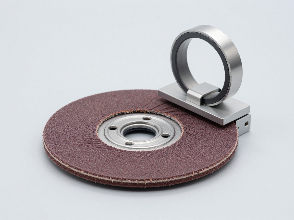
Corrosion is used to increase contrast between phases in metals or between layers of materials. With circuit boards and solder joints, etching is often used to highlight grain boundaries and intermetallic compound (IMC) layers.
| Situation | Should it corrode? | Reason |
|---|---|---|
| Measure the thickness of the plating layer | Usually not | The layer boundaries were clear enough by optical contrast |
| Evaluate solder joint grain structure | Yes | Contrast is needed to read grain size and morphology |
| Measure the intermetallic compound (IMC) layer | Depends on the situation | Light corrosion helps differentiate, strong corrosion can dissolve the very layer to be measured |
| Evaluate corrosion defects in products | No | Corrosion products are evidence, no further alterations should be made |
Safety principle: prepare two identical samples, corrode one sample and keep one sample intact. If the corrosion sample gives questionable results, there is still a control sample to test.
7. Five signs the sample has passed before measuring
- Flat surface, evenly reflective under slanted light.
- There are no visible scratches at working magnification.
- The boundaries between layers are sharp and not blurred.
- There are no gaps between the sample and the molded resin.
- The smallest details that need to be surveyed are still intact, without beveled or lost edges.
8. Frequently asked questions
Can a regular metal cutter be used to cut samples?
Shouldn’t. Conventional cutting machines generate great heat and force, easily deforming small solder joints and plating layers, making measurement results no longer reliable.
Can plastic or soft material samples be used as cross-sections?
Yes, but cold casting and finer abrasives should be used. Soft materials are prone to chamfering, so it is necessary to reduce force and shorten the time each step takes.
Does hand polishing give good enough results?
For screening purposes, it is possible. For the purpose of measuring thickness or analyzing intermetallic compound (IMC) layers, equipment with force and speed control should be used to reduce errors between measurements.
How long does it take for a sample to oxidize and need to be re-prepared?
Depends on material and storage conditions. For copper samples or samples with thin coatings, measurements should be made shortly after polishing and stored in a sealed container with a dehumidifier.
Is there any way to reduce the difference between the two technicians?
Yes: standardize the step-by-step process with fixed parameters, use the same materials, and periodically have two people prepare parallel samples from the same part for comparison.
9. Conclusion
The quality of cross-sectional images is determined in the four steps of sample preparation, not in the microscope. Each step has a characteristic error pattern, and each error pattern leaves a recognizable mark on the image.
Four things to do: control heat and coolant at the cutting step; Choose hot or cold casting according to the sample’s thermal sensitivity; downgrading abrasives in the correct order; and keep an uncorroded sample as a control.
References
- IPC-TM-650 Method 2.1.1 — Microsectioning, sample preparation steps.
- ASTM E3 — Guide to metallographic sample preparation.
- ASTM E407 — Corrosion of metals and alloys.
- IPC-A-600 and IPC-6012 — Technical criteria and requirements related to board cross-sections.
Related articles
- IPC-TM-650 2.1.1: standard microsection procedure
- Peeling of coating and loss of veins: read traces on cut surface
- Why do solder joints crack after thermal shock test? Read the marks on the cross-section
- Cross-section MLCC capacitors: cracks due to board flexing and delamination defects
- Cross-section through-hole solder joint: when does the pin solder joint crack?
- Choose the cutting position and send the cross-section sample: one wrong step and you will lose the entire data set
- Measuring dimensions on cross-sectional images: how to set the ruler to minimize the error?
- What is Cross Section? Why do we have to cut samples to evaluate solder joints and circuit boards?
- 10 circuit board defects can only be detected by cross-section
Discuss further
Disclaimer
This article is an interpretive content compiled by us; not legal advice. Enterprises need to compare relevant documents/standards verbatim before applying them to specific products.
See more: Copyright Policy & Disclaimer by ticforall.com.