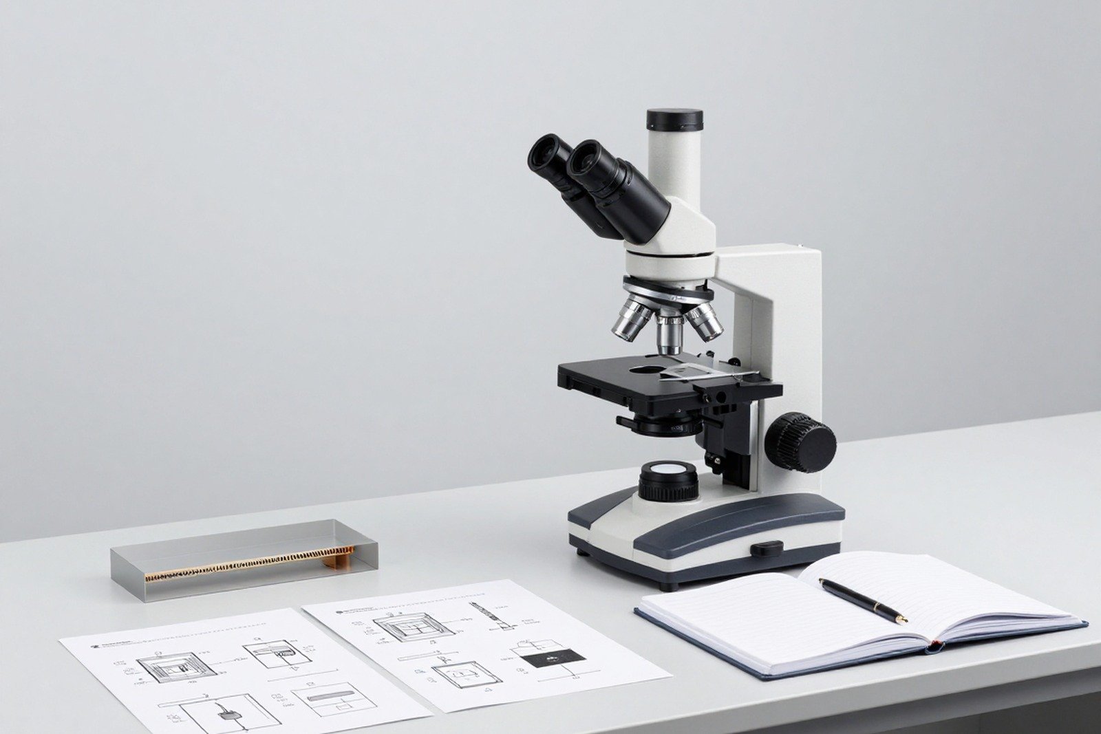
A good cross-section only answers the “what” question. The real question that gets a factory meeting is “why” — and the gap between the two is where many quality investigations go astray.
This article presents a five-step process from cross-sectional image to root cause, along with common mistakes and a set of criteria to know when the conclusion is strong enough.
1. Why is cross-sectional image not the answer by itself?
Cross-sectional images show the shape of the defect: where is the crack, what shape is the void, which layer is separated. But the same form can be caused by many different causes. If we jump to conclusions from the form, it’s easy to choose the wrong corrective action — and correcting the wrong area is more expensive than not correcting it.
Therefore, the investigation process must separate two things: describing the phenomenon, and tracing the cause. Step one is done by eye and microscope. Step two is made of data.
2. Five steps of investigation
| Step | Central question | Data needed | Output products |
|---|---|---|---|
| 1. Describe the phenomenon | What do you actually see? | Cross-sectional images with multiple magnifications, control sample images | The description is objective, without inference |
| 2. Identify the damaged floor | Is the defect in the base material, plating, solder joints, or components? | Image at high magnification at the transition zone | List of potentially relevant floors |
| 3. Build a hypothesis and timeline | At what stage can this phenomenon form? | Process diagram, step list, parameter data | List of hypotheses in order of priority |
| 4. Compare process data | Which hypothesis does the actual data support or rule out? | Heat log, force log, re-solder joint history, material change | The leading hypothesis remains |
| 5. Verify by reference test | Can the phenomenon be reproduced? | Test samples with controlled variables and control samples | Conclude the root cause with evidence |

3. Details of each step
Step 1 — Describe the phenomenon, not infer
- Record the location, size, and direction of each observed trace.
- Shoot at at least two magnifications: one to see the whole picture, one to see the details.
- Always take photos with the control sample at the same magnification.
- Do not use words that describe the cause in this step.
Step 2 — Identify the failed floor
Structural errors on circuit boards typically fall into one of four levels: substrate material, metal plating, solder joints, or component bodies. Determining the correct floor will localize the supplier and related process.
Step 3 — Build a hypothesis and assign a timeline
For each trace, list all the moments in the product life cycle that could have been created: material acquisition, solder jointing, paneling, assembly, testing, transportation, use. Then gradually eliminate based on the nature of the trace — for example, cracks with oxidized edges are difficult to form in the final step.
Step 4 — Compare process data
This is the step that distinguishes between speculation and conclusion. Data to compare: heat log of solder jointing furnace, contact time, number of re-solder jointing times, change of material supplier, change of machine parameters, clamping force and tightening torque.
Step 5 — Verify with control test
The conclusion is only as strong as it is reproducible: change exactly one variable, keep the rest constant, and see if the phenomenon appears as predicted. If it cannot be reproduced, it is necessary to reconsider the hypothesis instead of drawing conclusions based on feelings.
4. Two typical examples
| Phenomenon | Hypotheses are often chosen first | The right way to investigate |
|---|---|---|
| Crack at the heel of the solder joint | The immediate conclusion is lack of tin | Check the mechanical stress in the assembly and the thermal expansion differential before concluding on the amount of tin |
| Clear boundary between ball and solder paste | The immediate conclusion is a solder jointing error | Compare the thermal profile and surface oxidation status to determine the correct cause |
5. Common mistakes
- Jump from photo to conclusion: Skip the data collation step because the results look too obvious.
- Combine multiple causes into one conclusion: It’s generally written as “solder joint error” so no one knows what needs to be fixed.
- Missing control sample: If there are no samples from the same lot, all comparisons are only relative.
- Conclusion for the whole lot from one sample: a sample only represents itself.
- Ignore the possibility of errors due to sample preparation: Fake scratches, burrs and gaps can be read as real defects.
- Conclusion according to the requester: Choose the cause according to the ordering department’s expectations instead of according to the data.
6. Set of criteria to know if the conclusion is strong enough
- The specific failure floor has been identified, not just the general floor.
- There is a control sample under the same conditions.
- The hypothesis was verified by process data, not just by geometric inference.
- The possibility of error due to sample preparation was excluded.
- The phenomenon has been reproduced by controlled testing.
- Conclusions can be used to recommend specific actions for a specified step.

7. Frequently asked questions
How long does it take to walk all five steps?
Depending on the complexity and availability of process data. The most time-consuming step is usually step four, because process data is not always fully saved.
What if there is no process data?
It is still possible to narrow the scope using steps three and five: construct a hypothesis over time, then reproduce it with a controlled experiment. But the conclusion will be weaker and the limits need to be clearly stated.
Is it always necessary to find exactly one cause?
No. Many errors have multiple causes and effects. It is necessary to determine which causes are the main contributors and which can be intervened.
Which step is most often overlooked?
Step one. Many investigations begin with conclusions rather than with objective descriptions, leading to data collection in a predetermined direction.
When should an investigation be stopped?
Once there is a conclusion that leads to specific corrective actions and the corrective results can be verified with subsequent data. If this has not been done, the investigation has not ended.
8. Conclusion
Cross-sectional images are the starting point of the investigation, not the results. Its real value lies in the fact that it localizes the failure layer and provides a hypothesis that is specific enough to verify with data.
Four things to do: separate the description step from the inference step; always have a control sample; compare process data before concluding; and only end the investigation when the phenomenon can be reproduced under controlled conditions.
References
- IPC-A-610 — Electronic Assembly Acceptance Criteria.
- IPC-TM-650 Method 2.1.1 — Microsectioning.
- J-STD-001 — Requirements for electrical soldering and electronic assembly.
- IPC-6012 — Technical requirements for rigid printed circuit boards.
Related articles
- 5 strange marks on the cross-section: distinguish real errors from phenomena due to sample preparation
- Two Laboratories, Two Different Results: Why?
- 10 circuit board defects can only be detected by cross-section
- Why do solder joints crack after thermal shock test? Read the marks on the cross-section
Discuss further
Disclaimer
This article is an interpretive content compiled by us; not legal advice. Enterprises need to compare relevant documents/standards verbatim before applying them to specific products.
See more: Copyright Policy & Disclaimer by ticforall.com.