Home Blog Page 2

QCVN 4:2009/BKHCN: safety requirements for electrical and electronic equipment and Amendment 1:2016

0
Cover image of the article «QCVN 4:2009/BKHCN: safety requirements for electrical and electronic equipment and Amendment 1:2016»

Many household electrical appliances sold in Vietnam must obtain regulatory conformity certification and make a regulatory conformity declaration before being placed on the market, in accordance with QCVN 4:2009/BKHCN — the national technical regulation on safety for electrical and electronic equipment. The standard does not apply to “all electrical equipment” and does not apply to all voltage levels: the product list is in the Appendix, “low voltage power source” is a numerical definition, and Amendment 1:2016 virtually rewrites the wire and cable section.

1. What is QCVN 4:2009/BKHCN?

The regulation was issued together with Circular No. 21/2009/TT-BKHCN dated September 30, 2009. The structure includes 5 sections and an Appendix listing the list of equipment. The regulations have been revised once: Revision 1:2016 (Circular No. 21/2016/TT-BKHCN dated December 15, 2016, effective February 1, 2017), compiled by the Drafting Committee of National Technical Regulations on Low Voltage Electric Wires and Cables — so most of the new content revolves around electric wires and cables.

2. Scope of application: three questions must be answered first

  • Which product? Only equipment in the List in the Appendix (13 groups); The list may be amended, supplemented or removed by decision of the Minister of Science and Technology.
  • What power source? Connected directly or through a plug to a low voltage power source: 50–1000 V AC and 75–1500 V DC.
  • Where to use? In household, commercial and similar uses; Medical equipment and telecommunications equipment are excluded.
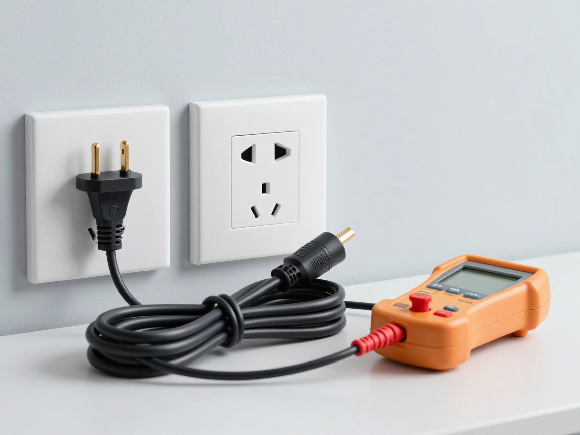
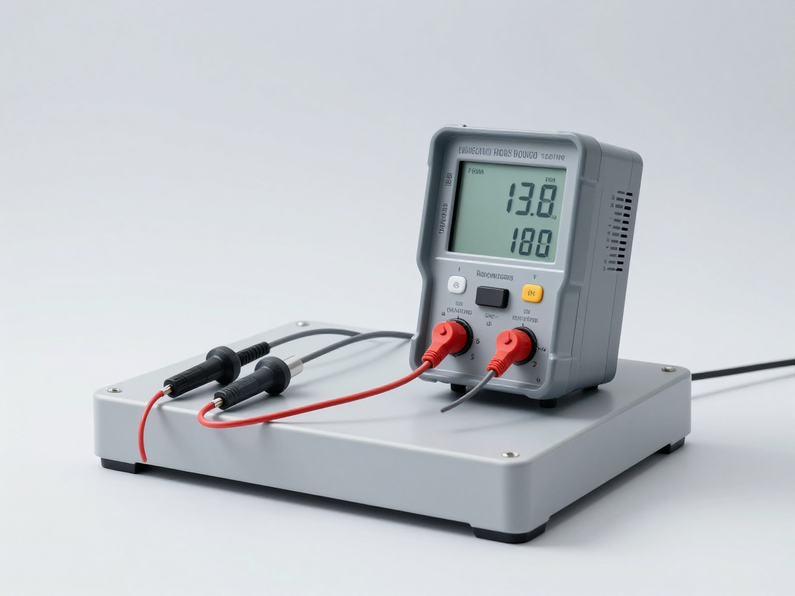
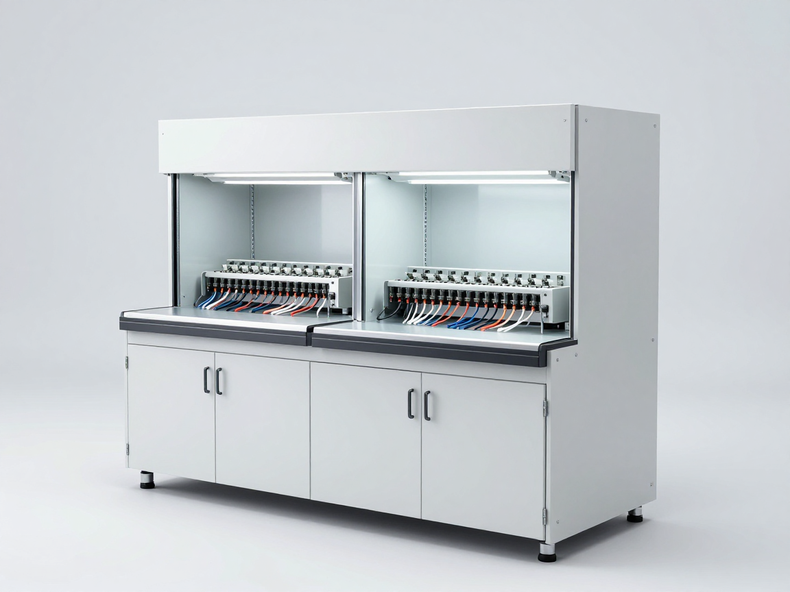
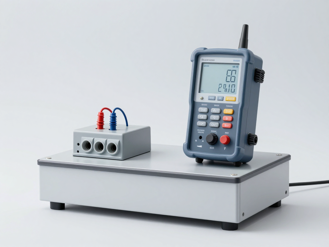
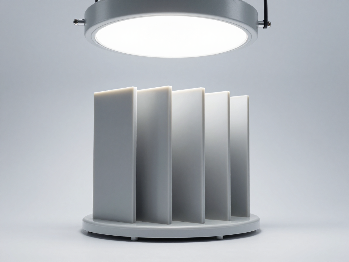
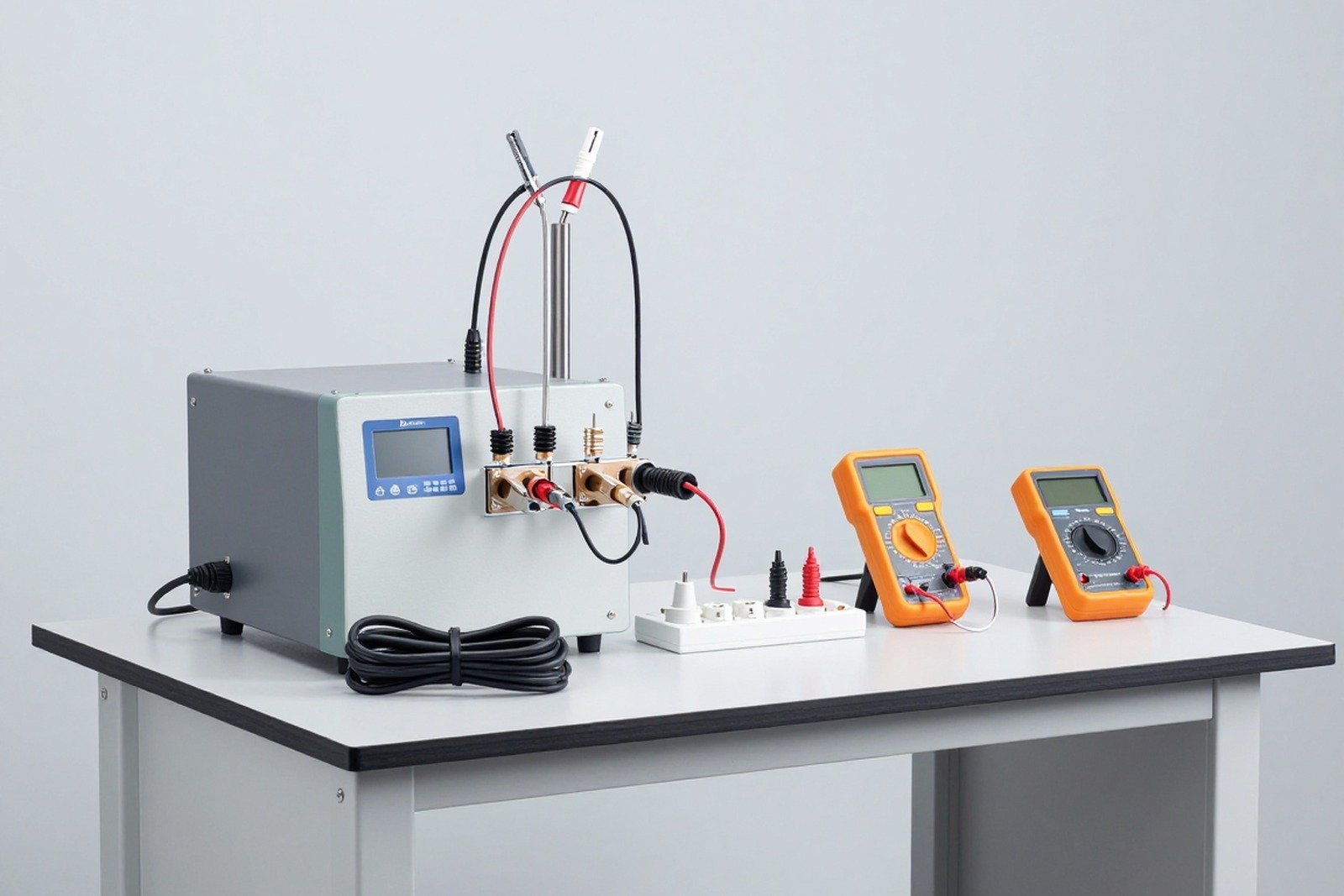
Electrical safety test bench with socket, plug, power cord and insulation measuring device
Three questions about scope determine the entire regulatory profile behind it.

3. List of 13 product groups and corresponding TCVN standards

  • Instant water heating electric appliance — TCVN 5699-2-35:2007
  • Electric water heating and hot water storage appliances — TCVN 5699-2-21:2007
  • Hair dryer and other hairdressing tools — TCVN 5699-2-23:2007
  • Kettle — TCVN 5699-2-15:2007
  • Rice cooker — TCVN 5699-2-15:2007
  • Electric fan — TCVN 5699-2-80:2007
  • Electric iron — TCVN 5699-2-3:2006
  • Microwave oven — TCVN 5699-2-25:2007
  • Electric oven, electric grill (portable type) — TCVN 5699-2-9:2004
  • PVC coated electrical wire up to and including 450/750 V — TCVN 6610 set; This heading was amended to “Electrical wires and cables” from Amendment 1:2016
  • Immersion type electric water heater (electric heating rod) — TCVN 5699-2-74:2005
  • Tea or coffee making equipment — TCVN 5699-2-15:2007
  • Hand dryer — TCVN 5699-2-23:2007

Most of the above standards belong to the TCVN 5699 (IEC 60335) series; kettles, rice cookers and shared tea/coffee makers use TCVN 5699-2-15, while hair dryers and hand dryers use TCVN 5699-2-23.

4. Safety requirements: the documents enterprises must prepare

Section 2 only states the principle: equipment must ensure safety in accordance with the corresponding TCVN – the technical content is in the standard itself, TCVN 5699 (IEC 60335) includes general requirements and product-specific parts. Test records must demonstrate the following groups of indicators:

  • Input power and rated current — the difference between the measured value and the value indicated on the label must be within the allowable tolerance.
  • Temperature rise — the temperature of the coil, conductor, shell and contact surface does not exceed the limit corresponding to the level of insulating material.
  • Insulation, leakage current and moisture protection — insulation resistance, leakage current and dielectric strength measured in working condition and after humidity treatment; liquid heating appliances also require overflow and drip tests.
  • Distances — clearance, creepage distance and solid insulation must meet the minimum values according to voltage level and pollution level.
  • Overload and abnormal operation — loss of water, locked rotor, forced thermostat cut-off: the appliance must not ignite or melt metal.
  • Thermal, fire and mechanical resistance — composite materials, current retention details, mobile device stability.

For 450/750 V PVC wires and cables, section 2.10 references four parts of TCVN 6610 (IEC 60227) according to structure: part 1 general requirements, part 3 unshielded cables for fixed installation, part 4 sheathed cables for fixed installation, part 5 flexible cables (wires). Level 450/750 V is the nominal voltage: 450 V between conductor and ground, 750 V between two conductors.

5. What does Amendment 1:2016 change?

  • Clause 2.10: replace “PVC coated power cord up to and including 450/750 V” with electrical wires and cables of 50 V or more — the applicable standards and labeling must be declared; Wires and cables under 50 V must still have their standards announced and clearly state the voltage level; Wires and cables without shielding and/or insulation do not fall under the corresponding standards.
  • Clause 3.1: provisions on placing products on the market — domestically produced and imported electrical and electronic equipment, excluding wires and cables below 50 V and above 1000 V, must be certified in accordance with the safety requirements in Section 2, and affixed with the regulation conformity mark (CR) before circulation.
  • Clause 3.2.3 and 3.3: additional mechanism acknowledge the assessment results of foreign organizations (Circular 27/2007/BKHCN) and appoint a foreign conformity assessment organization (Circular 26/2013/TT-BKHCN); Before recognition, the certification organization must ensure the capacity of the assessment organization and report to the Directorate for Standards, Metrology and Quality.
  • Clause 3.5: amending the registration basis according to Circular 28/2012/TT-BKHCN (manufacturing enterprises, documents according to Article 14) and Circular 27/2012/TT-BKHCN (importing enterprises, documents according to Article 6); Abolish clauses 3.5.3, 3.5.4, 3.5.5 — detailed list of records and record retention milestones of 10 years and 6 years are no longer valid.
  • Add Clause 4.3: Enterprises manufacturing and importing electric wires and cables must keep copies of quality standards for publication (Vietnamese, or English with an official Vietnamese translation), provide them when requested by competent authorities, and Keep records of announcement of applicable standards.

Circular takes effect from February 1, 2017; Electrical wires and cables apply Revision 1:2016 from August 1, 2018. The Circular does not apply to pre-installed wires and cables or parts of complete electrical and electronic equipment, and to wires and cables imported for installation into equipment and then exported (processing of goods for export, temporary import for re-export).
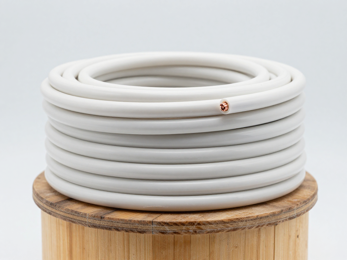
PVC-sheathed electrical cables and coils are placed on shelves in the warehouse, with cross-sections and outer shells visible
Amendment 1:2016 moves the 10th product group from “PVC-coated electrical wires ≤ 450/750 V” to “electrical wires and cables” — a significantly broader scope.

6. Electric wires and cables: standard declaration and labeling

For products of 50 V or more, clause 2.10 requires declaration of the applicable standards (TCVN, foreign, international or regional standards) with at least 5 items: DC resistance of conductor; sheath and insulation thickness; insulation resistance; voltage endurance; Tensile test before and after aging of insulation and sheath. Labeling must state origin and identification signs (voltage level, conductor and insulation material, cross-section, code/type), not easily erased; Labelling distance follows the published standard; where not specified, no more than 1000 mm between two consecutive markings (or 550 mm from the end of one marking to the start of the next).

7. Certification, CR mark, registration and record keeping

  1. Product labels according to the law on goods labels (now Decree 37/2026/ND-CP).
  2. Certificate of conformity certified by the organization designated or recognized carry out; method according to Article 5 and Appendix II Circular 14/2026/TT-BKHCN with 8 methods — groups of electrical and electronic equipment and wires and cables are using method 5 (testing representative samples and evaluating the production process or management system, with supervision) and method 7 (testing and evaluating batches).
  3. Conformity mark (CR) According to Clause 2, Article 4 of Circular 14/2026/TT-BKHCN: shape and size in Appendix I; shown on products, packaging, technical documents or labels; Easy to see and not easily erased.
  4. Register the declaration of conformity in the National database on measurement, standards and quality and receive a confirmation code; imported goods subject to state quality inspection; Keep records of declaration, maintain conformity and keep records to monitor the use of conformity marks.

Note on reference bases: QCVN 4:2009/BKHCN and Amendment 1:2016 refer to Decision 24/2007/QD-BKHCN and Circular 28/2012/TT-BKHCN; from 2026, Circular 28/2012/TT-BKHCN has expired (along with Circulars 02/2017 and 04/2025) and these contents are now according to Circular 14/2026/TT-BKHCN.

8. Update 2026: Circular 36/2026 and new legal framework

Circular No. 36/2026/TT-BKHCN (June 30, 2026, effective July 1, 2026) regulates the List of products and goods with medium-risk and high-risk levels; with electrical and electronic equipment and wires and cables, referenced standards is still QCVN 4:2009/BKHCN and Amendment 1:2016.

  • Appendix I, section 4 (high-risk) — electrical and electronic equipment using single-phase power up to 250 V, not including equipment that only runs on batteries, rechargeable batteries or DC power. Requirements: declaration of conformity based on the organization’s certification specified; methods 5 and 7; Imported goods undergo state quality inspection.
  • Appendix I, section 5 (high-risk) — low-voltage wires and cables used in electrical installations, up to 1000 V AC or 1500 V DC, with the exception of: PVC-coated wires of TCVN 6610 (up to 750 V) and extruded insulated cables of TCVN 5935-1 (0.6/1 kV). Requirements as section 4 Appendix I.
  • Appendix II, section 8 (medium-risk) — Electrical and electronic equipment that does not use 3-phase power, skin or hair care equipment, 1-phase fans ≤ 125 W and wires and cables that do not belong to TCVN 6610, TCVN 5935-1. Requirements: declaration based on the organization’s certification recognized or designated or self-assessment; Use methods 1, 5 and 7.

The basic legal framework will also change in 2026: the Law on Standards and Technical Regulations and the Law on Product and Goods Quality amended in 2025, accompanied by Decree 22/2026/ND-CP and 37/2026/ND-CP; Four Circulars dated April 9, 2026: 13/2026 (standard), 14/2026 (declaration of conformity and assessment method), 15/2026 (standards) and 16/2026 (mutual recognition, unilateral recognition of assessment results). The group of electrical equipment used for household electrical installations (for example, MCB circuit breaker ≤ 63 A) is referred to QCVN 25:2025/BKHCN from April 1, 2027.
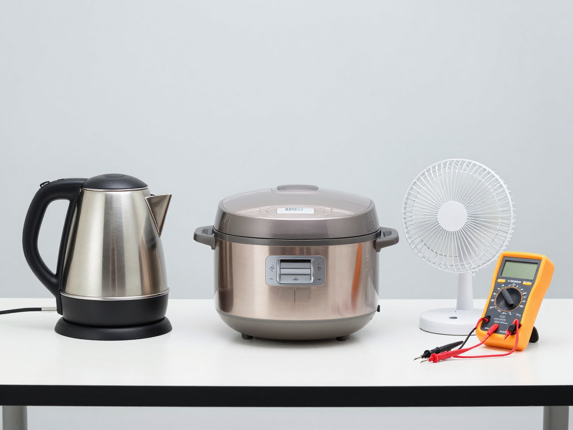
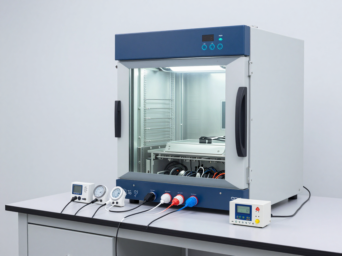
Household electrical appliances such as kettles, rice cookers and fans are placed side by side on a test table with measuring equipment
Same background standards but different requirements according to the risk level of the product.

9. Common trouble points for businesses

  • Think all electrical equipment is regulated — actually there are only 13 groups in the Appendix, and the List can be amended, supplemented, or canceled.
  • Choose the wrong standard part according to product structure; announced lack of targets; Wire/cable labels lack identification marks or have incorrect label repetition spacing; Incorrect use of record keeping milestones has been abolished.

10. Frequently asked questions

Is QCVN 4:2009/BKHCN still valid?

Yes. Circular 36/2026/TT-BKHCN still refers to QCVN 4:2009/BKHCN and Amendment 1:2016 for groups of electrical and electronic equipment, wires and cables; Procedures for declaration of conformity, CR mark and evaluation method are according to Circular 14/2026/TT-BKHCN.

Why do kettles, rice cookers and tea making utensils share the same standard?

Because they are all liquid heating appliances, TCVN 5699-2-15 applies to the same risk group: water flowing into the electrical part, water running out, heater heating and insulation deterioration when wet.

Are the cables installed in the device required to be declared compliant?

No. Circular 21/2016/TT-BKHCN excludes wires and cables that are already installed or are part of complete equipment, and wires and cables imported to be installed into equipment and then exported.

Do previously existing certificates and conformity marks have to be redone?

No. Article 17 of Circular 14/2026/TT-BKHCN allows continuing to use existing certificates and conformity marks until the end of their validity period, without having to re-register.

11. Conclusion

QCVN 4:2009/BKHCN is the foundation standard for electrical and electronic equipment safety in Vietnam: 13 product groups, each group associated with a corresponding TCVN standard. Amendment 1:2016 expands the scope to “electrical wires and cables”, requires declaration of standards with 5 basic items, tightens labeling requirements and adds the obligation to keep standard records. What needs to be done is still to identify the right product group, the right standard part, the right evaluation method – and use the correct current legal basis.

Related articles


Discuss further


    Disclaimer

    The article was compiled by us for interpretation; not legal advice. Source: QCVN 4:2009/BKHCN (Circular 21/2009/TT-BKHCN), Amendment 1:2016 (Circular 21/2016/TT-BKHCN), Circular 36/2026/TT-BKHCN, Circular 14/2026 and 16/2026/TT-BKHCN, Decree 22/2026 and 37/2026/ND-CP. Enterprises should compare the wording verbatim and consult the designated certification body. Copyright Policy & Disclaimer.
    Is 85/85 enough of a conclusion? Limits of hot damp test in reliability assessment

    0
    Cover image of the article «Is 85/85 enough of a conclusion? Limits of hot damp test in reliability assessment»

    In reliability assessment programs, “85/85” appears as a default condition: put the product in a high-temperature and high-humidity chamber, hold for a number of hours, remove it, measure again, and if it passes, conclude good reliability. That approach ignores an important question: what does the hot-wet test prove, and what does it not prove?

    This article analyzes the limitations of hot damp testing in assessing reliability, the conditions required for results to be meaningful, and how to present results so as not to be overinterpreted.

    1. What does hot moisture testing prove?

    In its most basic form, a hot-damp test proves a limited statement: under the conditions recorded, for the period of time tested, on the number of samples used, the sample does not exceed a predetermined level of degradation. That’s a conditional piece of evidence, not a general conclusion about longevity.

    • Prove: the ability of the sample to withstand the selected hot and humid conditions, within the tested time.
    • Prove: the existence or non-existence of some moisture-related damage mechanisms.
    • Cannot demonstrate: longevity under actual usage conditions, without acceleration modeling and validity data.
    • Cannot prove: behavior of other lots, if sample size is small and random sampling is not done.

    2. Four limits are often overlooked

    Limit Consequences if ignored
    There is no accelerated model Longevity cannot be inferred; The results are only meaningful under the conditions tested
    No electrical polarity control Ignore galvanic corrosion, leakage currents, and voltage-requiring mechanisms
    Do not measure parameter degradation Only know pass/fail without knowing reserve level
    The number of samples is too small or the sample is not selected randomly The conclusion has no statistical basis and is easily wrong with other batches

    The first limitation is the most important and also the most overlooked. Inferring life from an accelerated test requires: the assumption of a constant failure mechanism, a model describing the relationship between stress and failure rate, and experimental data at multiple stress levels to determine the model parameters. With a single data point at a stress level there is no model, only an observation.

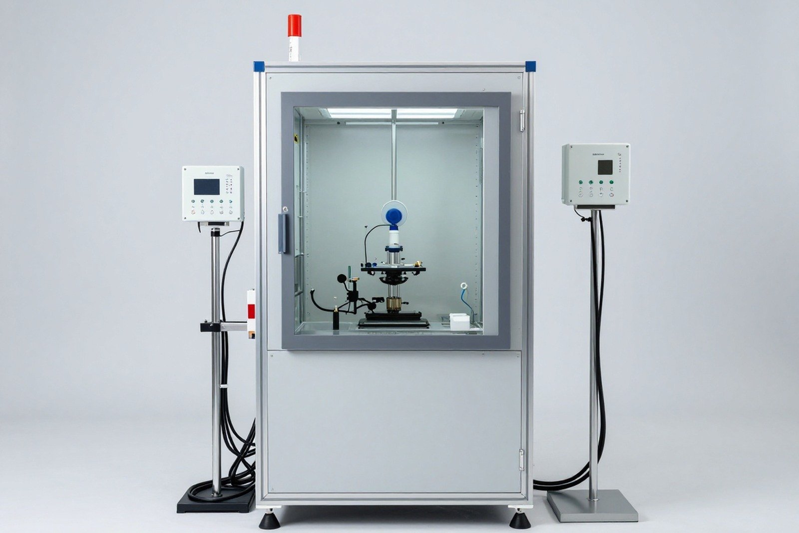
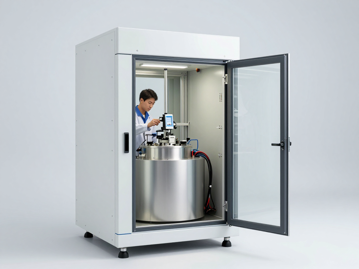
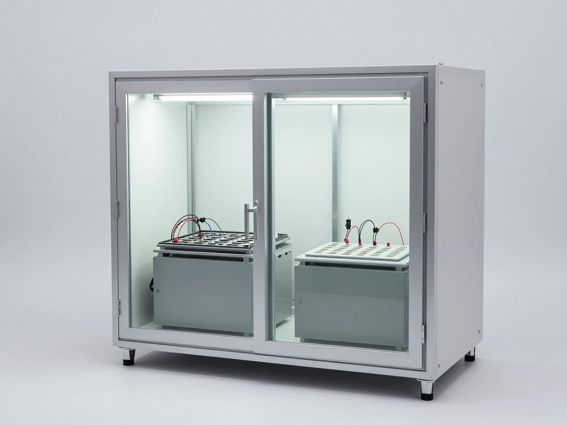
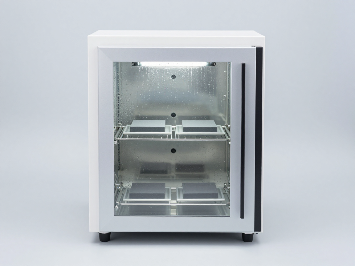
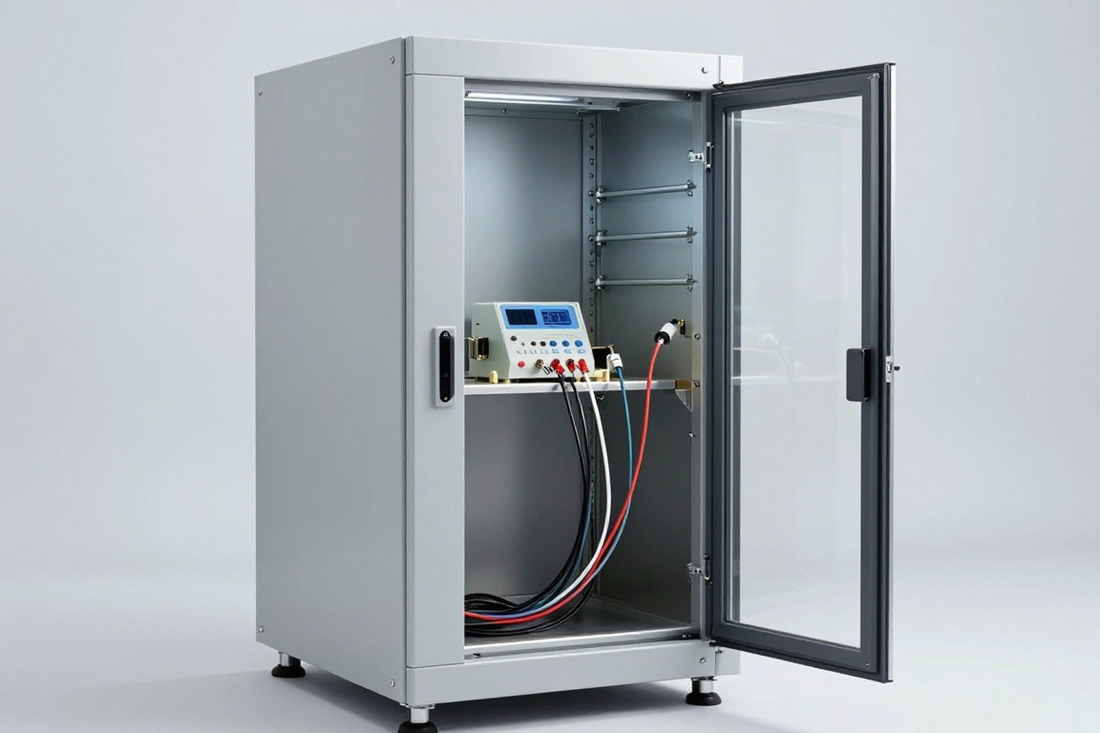
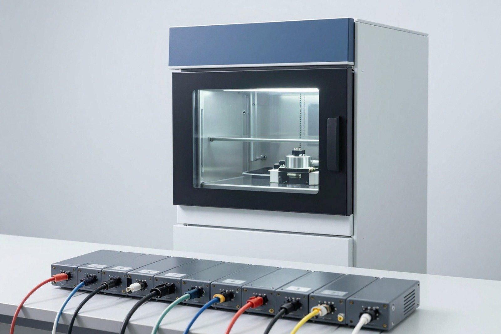
    Hot humidity test chamber with electronic modules placed on a tray
    Hot and humid conditions are only meaningful when recorded with time, tolerance, power supply status and number of samples.

    3. Why “85/85” is not a complete test

    The temperature-humidity pair does not adequately describe a test. For results to be reproducible and comparable, the test request must record at least:

    • Test code and standard part number — determines the condition structure (stable or cyclic, condensation or not).
    • Maintenance time — the main harshness variable with the moisture diffusion mechanism.
    • Transfer speed and time are stable — affects condensation and whether the sample reaches moisture balance or not.
    • Power supply and load status — If there is power supply, the capacity must be recorded because self-heating causes the actual temperature of the sample to be higher than the chamber temperature.
    • Pass criteria — predetermined by the allowable variation of the measurement parameter, not by “still active”.

    The second point about self-heating is often overlooked. A power supply device in a chamber has an actual component temperature higher than the chamber temperature — in some cases enough of a difference to completely change the dominant failure mechanism. How to place the sensor and measure the temperature of the loaded sample is presented in the article self-heating of the device.

    4. What to measure for meaningful results

    Parameter group For example The value of measuring
    Electrical insulation Insulation resistance, leakage current Sensitive to surface moisture and corrosion; early detection
    Function parameters Sensor sensitivity, error, signal loss Shows gradual deterioration rather than sudden failure
    Structural parameters X-ray, ultrasound, cross-sectional examination Detect delamination, cracks, and voids
    Appearance has classification Degree of corrosion, swelling, discoloration Visual evidence, requires predetermined criteria

    Important principle: measure attenuation at multiple time points, not just at the beginning and end. The decay line shows remaining reserves and helps detect early, regular damage, while a single pass/fail result gives just one bit of information.

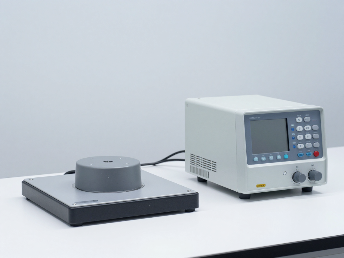
    Device for measuring leakage current and insulation resistance of the module after humidity test
    Measuring insulation parameters at multiple time points helps distinguish true deterioration from the influence of surface moisture.

    5. Properly combine with other tests

    The reliability of electronic products is not determined by one test. Hot moisture testing is often associated with:

    • Temperature change cycle to create repeated mechanical stress on the weld joint and the joining material.
    • Vibration and mechanical shock to detect mechanical defects before moisture penetrates.
    • Try hot and cold to separate the influence of pure temperature from the influence of moisture.
    • Test the function at boundary temperature to detect deviations that only appear under extreme conditions.

    When combining multiple tests, order is a variable. Placing the moisture test after the mechanical tests often aggravates the results, because mechanical damage opens the way for moisture. Once the order changes, the results are no longer comparable to previous attempts — so the order must be fixed in the records and kept the same between evaluations.

    6. Common mistakes and how to avoid them

    • Conclusion about longevity from a single moisture test — exceeds the logical limits of the data.
    • Temperature and humidity tolerances are not recorded — don’t know what conditions the actual sample accepts.
    • The test does not supply power but is called an assessment of operational reliability — omits a key set of mechanisms.
    • Evaluation by appearance — loss of ability to detect impairment that has not yet manifested on the outside.
    • The state and position of the sample in the chamber are not recorded — cannot handle differences between locations when there are abnormal patterns.
    • Do not confirm chamber capacity before a long campaign — small deviations over time accumulate into large moisture dose deviations.
    • Use the results of one batch for the entire product line — needs sampling and statistical facilities to do this.
    Data records and test samples are kept in the reliability laboratory
    A complete dossier including condition data, measurement results at each milestone and conclusions according to predetermined criteria is the basis for accepted results.

    7. Frequently asked questions

    How long is 85/85 considered enough?

    There is no general answer. Timing must be derived from the evaluation objective and from the acceleration model if longevity is to be inferred. If only proof of endurance is required, the time is chosen by the prescriber and must be clearly stated in the request.

    Can hot humidity testing replace longevity testing?

    No. The hot damp test is one data point at one condition. Life testing requires many data points, failure distributions, and assumptions about the mechanism — a significant amount of work and number of samples.

    Is it necessary to power the sample when testing 85/85?

    If the goal is to evaluate the reliability of the product in operation, power is needed — many failure mechanisms only appear when voltage is present. The no-power test is still valid, but the range of conclusions is narrower.

    How many samples is enough?

    Depends on the conclusion you want to reach: just observe the phenomenon, or confirm a level of confidence with a statistical basis. The number of samples should be chosen according to the objective of conclusion and sample provisioning for damage analysis.

    Does a result of 85/85 mean the product is durable?

    This means that the product does not exceed the allowable degradation level under the tested conditions, on the number of samples used. This is a conditional proof, not a guarantee of longevity or of other lots.

    How should the results be presented to the client?

    Specify the test code, conditions and tolerances, time, power supply status, number of samples, measurement parameters and variability, and predetermined pass criteria. Include original data and information confirming chamber capacity.

    8. Conclusion

    Hot moisture testing is an important tool for detecting moisture-related damage mechanisms, but it only provides conditional evidence: under the recorded conditions, for the time tested, on the number of samples used. Turning that evidence into conclusions about longevity is a logical leap that requires acceleration modeling and validity data.

    Three things should be done: write down enough information about the test conditions so that the results are reproducible; measure parameter deterioration at multiple time points instead of just pass/fail; and clearly state the limitations of the conclusions in the report, with recommendations for additional tests when high reliability is needed.

    References

    • IEC 60068-2-67 — Cy test: steady heat and humidity, mainly accelerated form for components.
    • IEC 60068-2-78 — Cab test: steady heat and humidity.
    • IEC 60068-2-30 — Test Db: hot-humidity cycle.
    • IEC 60068-2-38 — Z/AD test: combined heat-humidity cycle.
    • IEC 60068-3-6 and 60068-3-11 — Confirmation of chamber capacity and uncertainty of test conditions.
    • IEC 60068-1 — General provisions and guidance.

    Related articles


    Discuss further


      Disclaimer

      This article is an interpretive content compiled by us; not legal advice. Enterprises need to compare relevant documents/standards verbatim before applying them to specific products.

      See more: Copyright Policy & Disclaimer by ticforall.com.

      Confirmation of heat-humidity chamber capacity according to IEC 60068-3-6 and 60068-3-11

      0
      Cover image of the article «Confirmation of heat-humidity chamber capacity according to IEC 60068-3-6 and 60068-3-11»

      Just because the environmental chamber displays the correct temperature and humidity on the screen does not mean the conditions at the sample location are correct. The gap between “qualified chamber” and “qualified test test test specimen” is what IEC 60068-3-6 and IEC 60068-3-11 are about — two guidance documents for validating chamber capacity and calculating the uncertainty of test conditions.

      This article explains what thermal-humidity chamber validation entails, why it must be performed when the chamber is loaded, and how to use the validation results to protect the validity of the test report.

      1. What is chamber capacity confirmation?

      Performance confirmation is the procedure of measuring the characteristics of a test chamber and comparing them with the requirements of applicable standards. With heat-humidity chambers, the characteristics that need to be confirmed often include:

      • Stability: fluctuations in temperature and humidity at a point over time.
      • Uniformity: temperature and humidity differences between different points in the working space.
      • Deviation from set value (deviation): the difference between the displayed value and the value measured by the standard device.
      • Rate of change: the ability to raise and lower the temperature at the required rate, necessary for tests with a regulated speed.
      • Recovery time: ability to return to set conditions after opening the door or after introducing a sample.

      The first three characteristics are the framework of every validation report. Results must be documented with date, operator, standard equipment used and measurement data, so that they can be compared when required by the customer or accreditation organization.

      2. Where to measure and how many points to measure?

      The key to qualification is spatial sampling: if we only measure a point in the middle of the chamber, we know nothing about the area near the door, the area near the condenser or the top area. The standard approach is to select a set of measurement points distributed throughout the workspace (including corners and boundary locations), measure them simultaneously, and then calculate the difference between the points.

      Confirmation content How to do it Meaning of test results
      Stability at one point Record continuously over time at a fixed point Indicates whether the tolerance is tight enough for the test
      Spatial uniformity Measure multiple points simultaneously within the working range Indicate whether sample placement affects the results
      Difference with set value Compare with standard equipment with standard link Indicates whether the reported conditions match the actual conditions
      Load conditions Repeat the measurement when the chamber contains sample or dummy load Indicates actual test environment, not empty chamber
      Recovery time after opening Open the door according to procedure and then measure again Determine the impact of midterm testing
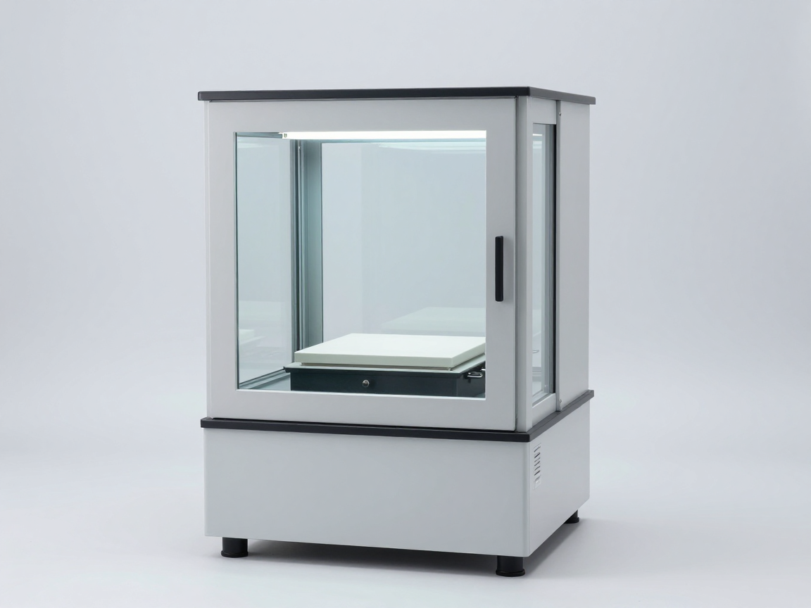
      Temperature and humidity sensors are located at many locations in the test chamber
      Arranging multiple sensors simultaneously in the working space is the basis for evaluating uniformity.

      3. Why is it necessary to confirm when the chamber is loaded?

      The empty chamber and the chamber with sample are two different thermal systems. Samples and racks put into the chamber change:

      • Air flow: The sample hinders circulation, creating stagnant air zones and larger temperature differences.
      • Thermal inertia: The sample mass needs time to reach temperature, so the holding time must be long enough.
      • Moisture exchange: The hygroscopic material of the sample causes the chamber humidity to change, especially with large samples.
      • Self-heating: Samples with power supply generate heat, creating a local difference.

      Therefore, an empty chamber validation report only proves the capacity of the chamber, not the conditions at the sample. The next step — measuring the temperature at the sample itself under load conditions — is presented in the text cold/hot test with load: place the sensor and measure the sample temperature.

      4. Uncertainty of test conditions

      Confirmation results always include a degree of uncertainty. Calculation of uncertainty includes: uncertainty of the reference device and reference chain, uncertainty due to spatial sampling, the effect of chamber running on time, and the resolution of the recording system.

      Uncertainty component Origin
      Standard equipment Error of the sensor and calibration chain, drift over time
      Spatial sampling The number of measuring points is small compared to the chamber volume, the measuring points are not representative
      Variation over time Control cycle of the chamber, sampling time
      Effect of load Shielding, dehumidifying, self-heating model
      Human manipulation Place the sensor, open the chamber door, time to record data

      Once the uncertainty is known, the evaluation of the test results becomes clear: if the error is within the uncertainty, it cannot be concluded that the sample is defective; On the contrary, a deviation that exceeds the uncertainty is strong technical evidence — this principle applies directly when developing criteria as in the article. Pass/fail criteria after environmental testing.

      The software records temperature and humidity from multiple measurement channels
      The multi-channel recording system allows simultaneous assessment of temporal stability and spatial uniformity.

      5. Confirmation cycle and records to be kept

      • Before putting the chamber into use for a new test: confirm at the correct temperature and humidity range to be used.
      • According to regular cycles: according to internal regulations and requirements of the accreditation system; Frequency depends on usage and severity.
      • After repair, major maintenance or room relocation.
      • When the chamber has a larger load than normal or change the rack configuration.

      Records should be kept: measurement point location diagram, original measurement data, standard equipment used with calibration paper, loading conditions when measuring, conclusions about the ability to meet the requirements of the test, and the person performing the test.

      6. Common mistakes and how to avoid them

      • Only record the value on the chamber display without independent measuring equipment — it is impossible to demonstrate real conditions.
      • Confirm the chamber is empty and then use it for the loaded chamber — lack of evidence of conditions at sample.
      • Measure only one point in the center of the chamber — ignores misalignment between locations, which is a common source of dispute.
      • The location of the sensor is not recorded — results are not reproducible.
      • Ignore uncertainty when evaluating — pass/fail conclusions based on errors contained in measurement noise.
      • Do not compare the time of calibration of standard equipment — records lose value before the evaluation organization.
      Technician checks the measurement configuration of the climate test chamber
      Validation must be performed with chamber configuration and sample stacking identical to actual use.

      7. Frequently asked questions

      Does chamber capacity confirmation require calibration?

      Not consistent. Calibration applies to measuring equipment (sensors, recording systems). Validation applies to the chamber as a system, assessing the ability to create and maintain conditions within the workspace.

      Is a stand-alone measuring device needed when the chamber already has sensors?

      Needed, because the chamber sensor is part of the system being evaluated. Independent measuring equipment with standard links is the basis for conclusions.

      If the chamber meets the confirmation requirements, are you sure the test results are correct?

      Not enough. It is also necessary to control the way the sample is mounted, the sensor position on the sample, the holding time for the sample to reach equilibrium, and the time to measure parameters after the test.

      How much uncertainty is acceptable?

      Depends on the tolerance required by the test: the uncertainty must be significantly less than that tolerance. Specific criteria need to be compared verbatim to the guidance documents and customer requirements.

      Can chamber manufacturer’s confirmation results be used?

      Should only be used as reference information. Validation should be performed at the installation site, with actual usage configurations, and repeated periodically.

      Can an unaccredited testing room self-certify the chamber?

      You can do it yourself according to the instructions, but when the results must be used for documents that need to be recognized, it is recommended that standard equipment be calibrated and fully documented.

      8. Conclusion

      Confirming thermal-humidity chamber capacity is the foundation of any valid climate test. It turns a “pass chamber” into a “sample received at the right conditions within a specified time period”, and includes an uncertainty to make a pass/fail conclusion valid.

      Three things to do: confirm the correct temperature-humidity range and the correct load configuration to be used; Measure at many points distributed in the working space with independent standard equipment; and keep complete records including measurement point diagrams, original data and calibration papers.

      References

      • IEC 60068-3-6 — Validation of temperature and humidity chamber capacity.
      • IEC 60068-3-11 — Calculation of uncertainty of conditions in a climatic test chamber.
      • IEC 60068-3-5 — Validation of temperature chamber capacity for cold and dry heat testing.
      • IEC 60068-3-7 — Measurement in loaded chambers, guidance on cold and hot loaded testing.
      • IEC 60068-1 — General provisions and guidance.

      Related articles


      Discuss further


        Disclaimer

        This article is an interpretive content compiled by us; not legal advice. Enterprises need to compare relevant documents/standards verbatim before applying them to specific products.

        See more: Copyright Policy & Disclaimer by ticforall.com.

        Cx test (IEC 60068-2-66): hot moisture in pressurized steam and when needed

        0
        Cover image of the article «Cx test (IEC 60068-2-66): hot moisture in pressurized steam and when needed»

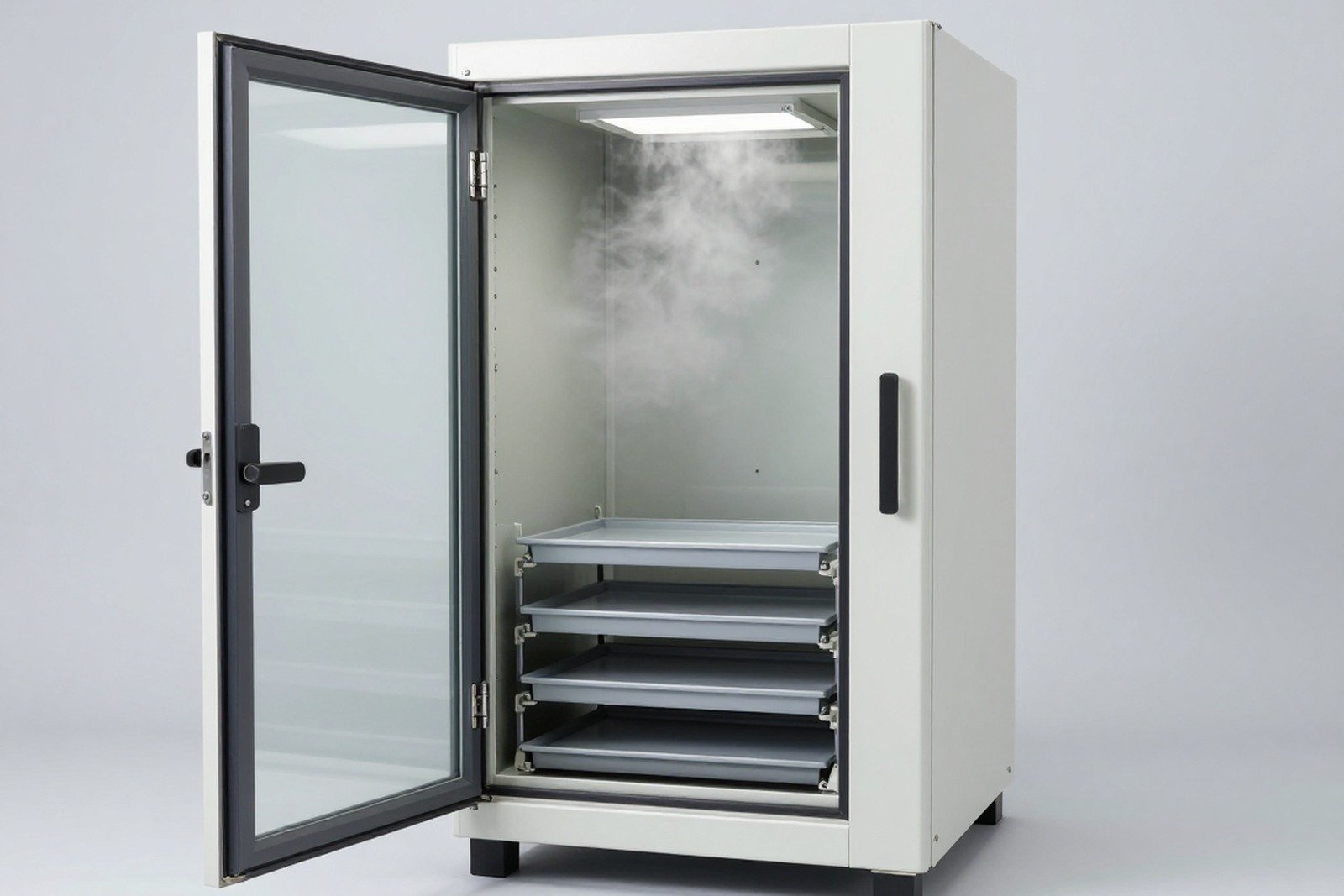
        Most of the hot damp testing in IEC 60068 takes place at atmospheric pressure. The Cx test according to IEC 60068-2-66 is an exception: the sample is placed in unsaturated steam but at a pressure higher than atmospheric pressure. This allows high temperature and high humidity to be achieved simultaneously without boiling or spraying water directly onto the sample.

        This article explains how Cx works, when this test is really necessary, and what technical points must be checked for the results to be valid.

        1. What question does the Cx test answer?

        Cx is an unsaturated pressurized vapor test. The test chamber operates like a controlled pressure cooker: high pressure increases the boiling point of water, allowing the chamber to achieve high temperatures combined with high humidity — something that at atmospheric pressure can only be done by humidifying or heating water, with many uncertainties.

        • Can the product withstand harsh hot and humid environments for short periods of time, at a level that is difficult to achieve with atmospheric methods?
        • Does moisture penetrate quickly through gaskets, membranes, and coatings when there is a pressure difference?
        • Do organic materials and thermoplastics lose mechanical properties at high humid temperatures?
        • Are the results reproducible between different test chambers?

        2. Why use pressurized steam?

        At atmospheric pressure, water boils at 100 °C. If you want to test at temperatures above 100 °C with high humidity, you must increase the pressure. This principle provides three benefits:

        • REACHes high temperatures with real humidity instead the dry gas is heated — something that is difficult to do with a conventional chamber.
        • Accelerates the procedure of moisture penetration thanks to differential pressure, suitable when quick results are needed for small components or assemblies.
        • Reduced dependence on mist spraying — a large source of error in conventional hot humid chambers (water drops do not evaporate completely, remaining on the sample).

        In turn, the test places high demands on equipment and safety. The sample and materials used must withstand high temperatures, and the procedure must control pressure release before opening the chamber to avoid sudden condensation on the sample.

        Characteristics Cx (pressurized steam) Cab (regular hot and humid)
        Conditions High temperature, high humidity, above atmospheric pressure Temperature and humidity at atmospheric pressure
        How to humidify Steam in a closed chamber is pressurized Usually by misting or active humidity control
        Harsh level achieved Higher, difficult to reach by atmospheric method Limited by boiling temperature and moisture retention capacity
        Device requirements Pressure chamber, pressure control and pressure release Standard environmental chamber
        Fits Small samples, components, high heat resistant materials Universal products and assemblies
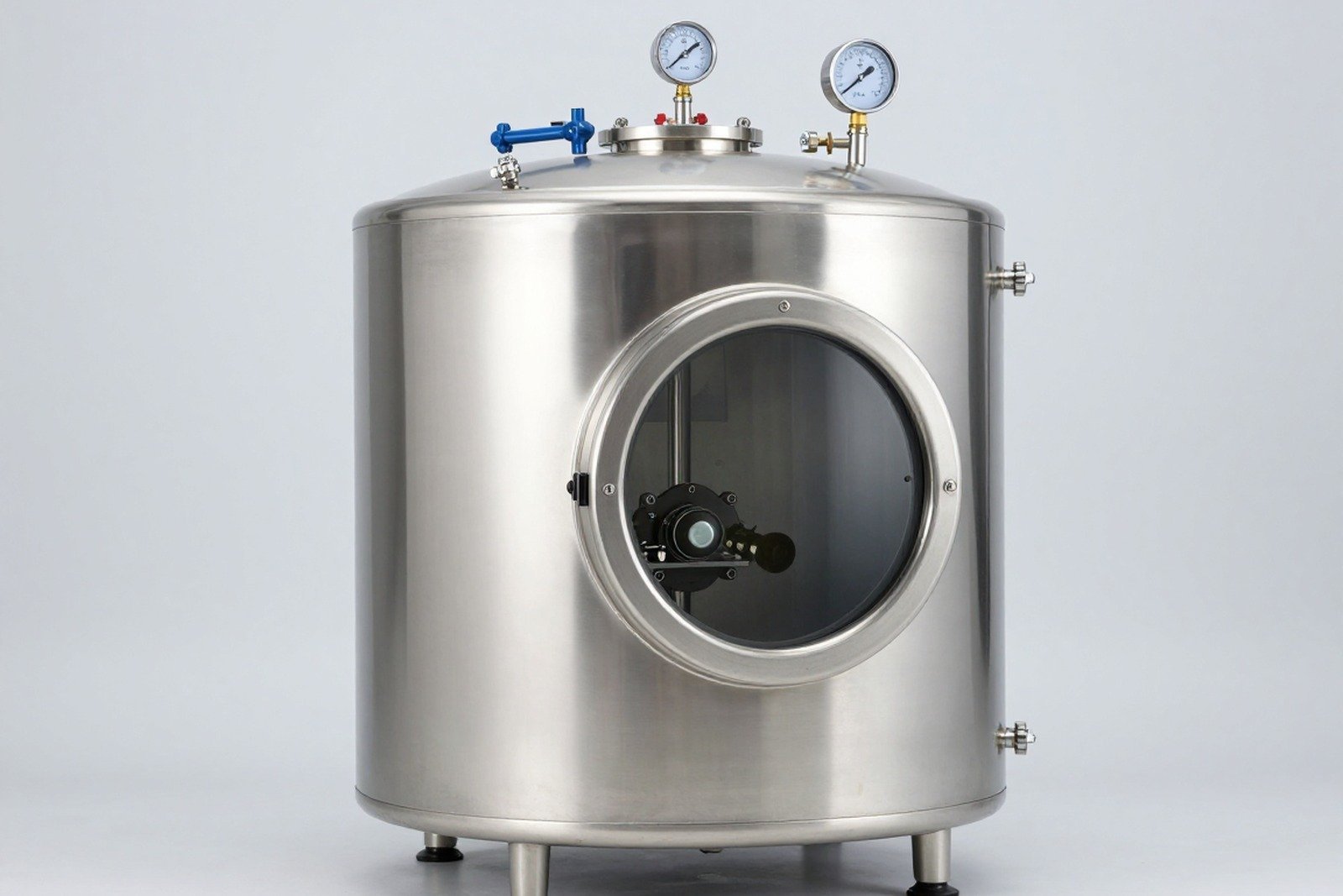
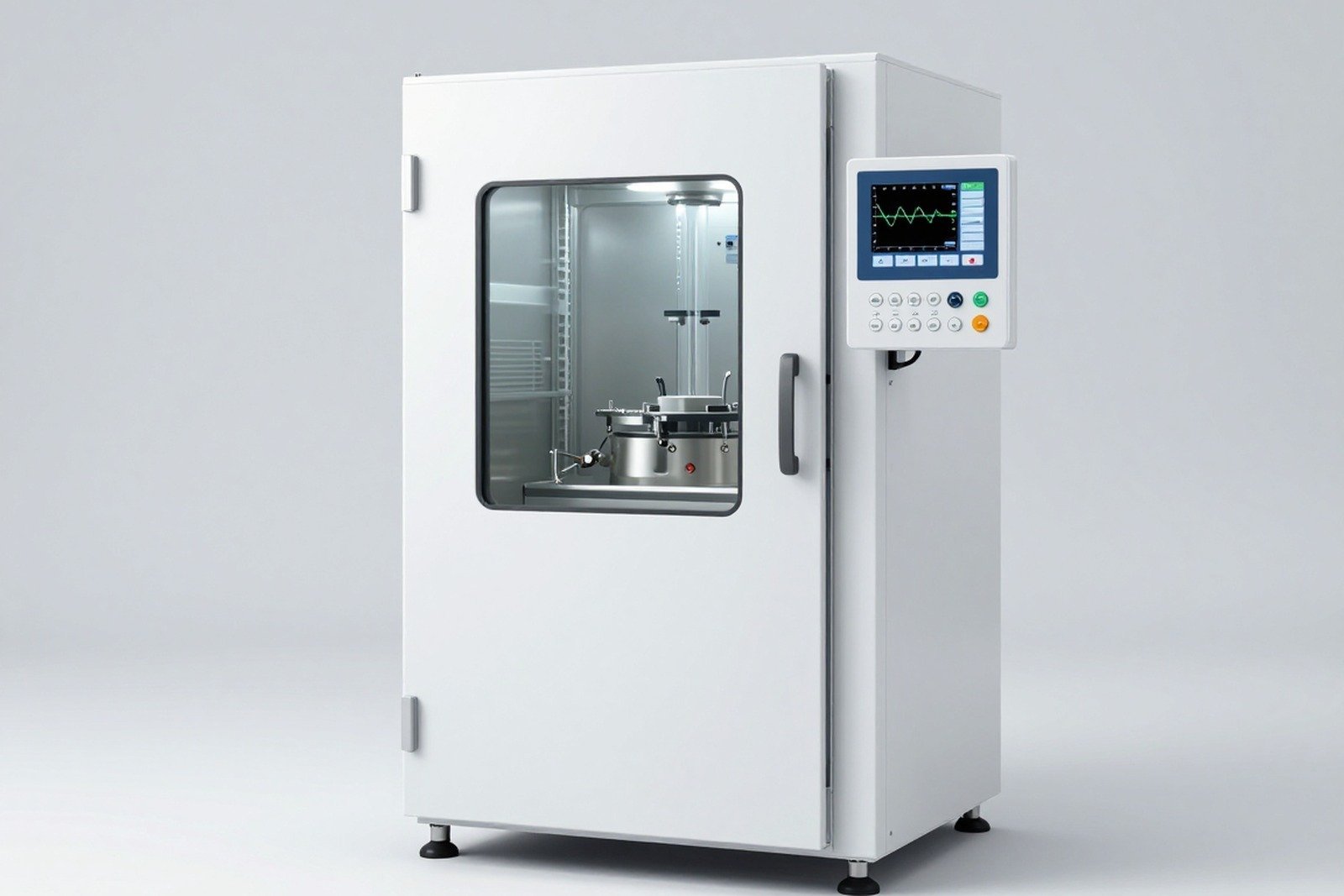
        Pressurized steam test chamber with observation window
        The Cx chamber must control pressure, temperature and pressure release procedures to prevent unplanned condensation.

        3. When is Cx really needed?

        Cx is not a common test. It should only be chosen when there are clear technical reasons:

        • Need hot and humid conditions beyond the capacity of the atmospheric chamber while still retaining true humidity, not dry heat air.
        • Evaluate packaging materials, gaskets, and protective films of components at high severity levels in a short time.
        • Research on damage mechanism under acceleration conditions, with controlled variables.
        • Where customer specifications or industry standards properly cite this test.

        Conversely, with finished products, equipment with organic materials or ventilation lines, Cx can cause damage that is not representative of the environment of use. In that case, damp heat tests at atmospheric pressure are often more reasonable — compare options below Select the environmental test according to the usage environment.

        4. Implementation sequence

        1. Check the heat resistance of the sample: confirm that internal materials and components can withstand test level temperatures; This is the prerequisite step.
        2. Confirm chamber capacity: Check temperature and humidity distribution, pressure holding ability, and pressure release procedures.
        3. Set initial milestones: Measure electrical parameters, check appearance, take photos.
        4. Insert the sample and run the condition: raise the temperature and pressure according to the procedure; keep stable for the specified time.
        5. Termination and pressure release: Release pressure in a controlled sequence to limit sudden condensation; Remove the sample to a dry surface.
        6. Recovery and assessment: Stabilize the sample, re-measure parameters and compare with the original benchmark.

        5. Factors that determine results

        Factor Why is it important?
        Chamber pressure Determine the boiling point and thus the temperature-humidity relationship obtained
        Pressure increase and decrease speed Affects the level of condensation on the sample surface
        Sample materials Organic materials, gaskets, and membranes can be damaged by heat before moisture
        Chamber volume relative to sample Large samples take up volume, changing the thermal dynamics of the chamber
        Maintenance time Determine the degree of moisture penetration and cumulative deterioration
        Pressure release process If rinsed too quickly, the sample will be wet and the post-test measurement results will no longer be accurate
        Pressure and temperature control panel of steam test chamber
        Simultaneous monitoring of pressure, temperature and humidity is required to demonstrate a valid Cx test.

        6. Common mistakes and how to avoid them

        • Choose Cx because it’s “harsher” without checking that the failure mechanism is still correct — the result may be unusable.
        • No pressure recorded in records — lack of pressure makes it impossible to repeat the test.
        • Releasing pressure too quickly — the sample is strongly condensed, causing damage not related to the test and misleading measurement results.
        • Place samples with batteries or materials that are poorly heat-resistant — safety risks and artificial damage.
        • Do not measure parameters before testing — loss of reference point, especially dangerous when the test causes rapid deterioration.
        • Use Cx results to infer lifespan without the acceleration model and accompanying assumptions.
        Check the appearance of the component sample after the pressurized steam test
        The sample after Cx needs to be visually examined and analyzed for its mechanism before drawing technical conclusions.

        7. Frequently asked questions

        Are Cx and Cx the same test?

        In the classification of IEC 60068, symbols starting with C belong to the group of hot damp tests, distinguished by the second letter and the corresponding standard part number. It is necessary to clearly state the standard part number in the dossier to avoid confusion — see how to read IEC 60068 test designations in the related article section.

        Is the Cx test dangerous?

        Pressurized chambers require their own safety procedures, including working pressure limits, relief valves, chamber opening procedures, and periodic equipment inspections. This is why many testing laboratories do not have this test available.

        Which samples should not be tested for Cx?

        Products containing batteries, fusible materials, low heat resistant coatings, or sealed structures may deform due to differential pressure. Risk assessment needs to be done before trying.

        How long does the Cx test take?

        The standard provides selected time ranges; This test is usually shorter than that of a stable hot humid at atmospheric pressure because the conditions are more severe. It is necessary to compare the standard verbatim when making requests.

        Can Cx be combined with other tests?

        Yes, but it needs to be placed in a reasonable order: usually placed after mechanical defect detection tests so that both stress sources can be combined. The order affects the final result so it must be agreed in writing.

        Can Cx results be used for declaration of conformity documents?

        Only if the applicable text or technical requirement cites the correct test, and the laboratory has accredited capacity for that test.

        8. Conclusion

        Cx is a hot-humidity test in pressurized steam — a unique tool for achieving hot-humidity conditions at levels not possible with an atmospheric chamber, suitable for small samples and high-temperature materials. The value of the test depends entirely on the control of pressure, temperature, humidity and pressure release procedure.

        Three things to do: confirm the sample can withstand the temperature and pressure differential of the test; prescribe and document pressure release procedures; and document pressure – temperature – humidity data over time as reproducible evidence.

        References

        • IEC 60068-2-66 — Cx test: steady hot damp in pressurized unsaturated steam.
        • IEC 60068-2-78 — Cab test: steady heat and humidity.
        • IEC 60068-2-67 — Cy test: steady heat and humidity, mainly accelerated form for components.
        • IEC 60068-3-6 and 60068-3-11 — Confirmation of environmental chamber capacity and uncertainty.
        • IEC 60068-1 — General provisions and guidance.

        Related articles


        Discuss further


          Disclaimer

          This article is an interpretive content compiled by us; not legal advice. Enterprises need to compare relevant documents/standards verbatim before applying them to specific products.

          See more: Copyright Policy & Disclaimer by ticforall.com.

          Cy test (IEC 60068-2-67): steady heat and humidity accelerates components

          0
          Cover image of the article «Cy test (IEC 60068-2-67): steady heat and humidity accelerates components»

          The term “85/85” has almost become an alternative term for hot humidity testing in the electronics industry. Many people say 85/85 without knowing which test in the IEC 60068 series they are talking about. In fact, the combination of 85 °C and 85 % RH is often associated with the Cy test according to IEC 60068-2-67 — a stable hot damp test under accelerated conditions, with the main object being the component.

          This article explains how Cy differs from Cab and Cx, why acceleration conditions are only suitable for certain product groups, and what needs to be agreed upon with the testing laboratory before introducing Cy into a reliability assessment program.

          1. What question does the Cy test answer?

          Cy is a steady heat and humidity test in accelerated form, mainly for components. Samples are kept at high temperature and high relative humidity, under stable conditions, for long periods of time. Compared to Cab — which uses ambient temperature — Cy pushes temperatures higher to accelerate moisture-dependent deterioration mechanisms.

          • Does the packaging material absorb too much moisture and change the electrical parameters of the component?
          • Does corrosion occur on component pins, internal wires, or solder joints?
          • Are protective coatings and adhesives still effective under prolonged harsh conditions?
          • Is the stability of the parameters within allowable limits after hundreds to more than a thousand hours?

          Because it is an accelerated test, Cy is often used in component reliability assessment, supplier qualification, and comparing material options — things that require results within weeks rather than months.

          2. Cy, Cab and Cx: three moisture tests, three different targets

          Criteria Cy (60068-2-67) Cab (60068-2-78) CX (60068-2-66)
          Nature of conditions Stable heat and humidity, accelerated form Humidity and heat are stable at environmental levels Steam is pressurized, not saturated
          Main object Components Products, assemblies The product requires special humidity conditions
          Target Shorten the time to evaluate moisture-related mechanisms Evaluate long-term humidity effects at real-world environmental levels Creates humid conditions with tightly controlled pressure and temperature
          Risk of misuse Acceleration conditions can create mechanisms that do not exist in reality Mechanisms requiring higher stresses were not detected Failure to regenerate without pressure control

          It should be noted: Cy is not an “upgraded” version of Cab. The choice of Cy is an engineering decision that must be based on the failure mechanism to be evaluated and on whether the acceleration condition still properly simulates that mechanism. How to write codes and test conditions in the request, see the article Read the IEC 60068 test designations correctly.

          High precision temperature and humidity test chamber with components tray
          Cy’s accelerated conditions require the chamber to maintain high temperature and humidity with tight tolerances for weeks.

          3. Why acceleration conditions cannot be used for all products

          The principle of accelerated testing is to cause damage to occur faster, but with the same mechanism. When pushing the temperature too high, three risks appear:

          • Switch failure mechanism: At high temperatures, stress can be applied to a mechanism different from the actual working mechanism, so the results are no longer predictable for the conditions of use.
          • Exceeding material limits: glue, gasket, thermoplastic with phase transition temperature; If you cross this threshold, try another product.
          • Deviation due to self-heating: At high chamber temperatures, the self-heating of a resistive device becomes relatively smaller, distorting the correlation with real conditions.

          Therefore, with finished products, large sizes or organic materials, it is often necessary to choose a temperature level lower than the maximum acceleration level, accepting a longer test time.

          4. Implementation sequence

          1. Confirm chamber capacity: Check temperature and humidity uniformity at the correct level to be used, especially at the sample location.
          2. Set initial milestones: Measure typical electrical parameters on the entire sample, check appearance, record batch number.
          3. Sample layout: clearly state the location; Avoid leaving samples shielding each other or placing them close to moisture sources, causing local deviations.
          4. Maintain conditions: Keep temperature and humidity stable for required time, record data continuously.
          5. Check by landmark: Sampling at time points to build a decline curve, instead of just measuring at the beginning and end.
          6. Recovery and assessment: Bring the sample to standard conditions, treat surface moisture, measure again and compare with the original mark.

          5. Factors that determine results

          Factor Influence
          Test temperature and humidity level Determine the rate of deterioration and whether the failure mechanism is still correct
          Test time With moisture diffusion, time is the key variable
          Power supply status Power supply increases local heat and creates electrochemical corrosion
          Coatings and packaging materials Determines the speed at which moisture reaches the inside of the component
          Chamber stability over time Small deviations over many weeks accumulate into large deviations in moisture dose
          When and how to measure Measuring while the surface is still wet will skew the conclusions
          The device records temperature and humidity data in the long-term test chamber
          Continuous data over several weeks is indispensable for long-term hot and humid tests.

          6. Common mistakes and how to avoid them

          • Use 85/85 as a default value for all products — can create failure mechanisms that do not exist in reality.
          • No test clearly stated in the records — “85/85” is not enough for standard comparison.
          • Measure only at the beginning and end — loss of information about degradation kinetics, inability to distinguish between early and late damage.
          • Do not check appearance before testing — does not distinguish between pre-existing defects and damage caused by testing.
          • Place samples too close together — local humidity varies, results between samples are not comparable.
          • Use Cy results to conclude about real life expectancy without the acceleration model and accompanying assumptions.
          Technician measures component parameters after accelerated heat and humidity test
          Measuring parameters on a large enough number of samples at each time point helps detect silent deterioration before components completely fail.

          7. Frequently asked questions

          What test is 85/85 in IEC 60068?

          Depends on context. In the IEC 60068 series, hot and humid conditions at high temperature, high humidity, and stability, used for components are often associated with Cy testing. When making records, always write down the test code and standard part number, not just the temperature-humidity pair.

          How long does Cy last?

          The standard provides time levels to choose from, usually measured in many hundreds of hours to more than a thousand hours. The specific time is chosen by the prescriber according to the assessment objectives and must be compared verbatim to the standards.

          Can replacing Cy with Cab last longer?

          The two tests create different stress levels. Extended cab environmental rating; Cy rates at acceleration. Replacement is only accepted when technical requirements allow and there is a correlative basis.

          Does Cy need to supply power to components?

          If the target includes galvanic corrosion and degradation due to bias voltage, power is required. If only packaging materials and moisture absorption are to be evaluated, an unpowered test can be performed. The status must be clearly stated in the application.

          Can Cy results be used to accept parts batches?

          It is possible, but acceptance criteria, number of samples, and allowable variation of parameters must be predetermined. “Still active” should not be used as the sole criterion.

          Is Cy suitable for circuit boards with soldered components?

          Okay, and this is a common application when evaluating assemblies. It is necessary to pay attention to whether the board material and coating glue can withstand the test temperature or not.

          8. Conclusion

          Cy is an accelerated steady-state heat and humidity test primarily for components, and is a test that is often mistakenly referred to as “85/85” without the test code. Acceleration conditions are only valid when the damage mechanism remains the same as in use conditions, so choosing the temperature – humidity level must have a technical basis, not based on habit.

          Three things to do: write down the test code and standard part number in the file; Measure parameters at multiple time points to see decline trends; and confirm that the chamber capacity is at the correct level under the conditions in which it will be used, for as long a period of time as actually tested.

          References

          • IEC 60068-2-67 — Cy test: steady heat and humidity, mainly accelerated form for components.
          • IEC 60068-2-78 — Cab test: steady heat and humidity.
          • IEC 60068-2-66 — Cx test: steady hot damp in pressurized unsaturated steam.
          • IEC 60068-3-6 and 60068-3-11 — Confirmation of environmental chamber capacity and uncertainty.
          • IEC 60068-1 — General provisions and guidance.

          Related articles


          Discuss further


            Disclaimer

            This article is an interpretive content compiled by us; not legal advice. Enterprises need to compare relevant documents/standards verbatim before applying them to specific products.

            See more: Copyright Policy & Disclaimer by ticforall.com.

            Z/AD combined heat-humidity cycle (IEC 60068-2-38) for electronic components

            0
            Cover image of the article «Z/AD combined heat-humidity cycle (IEC 60068-2-38) for electronic components»

            Within the IEC 60068 family of climatic tests, the Z/AD test according to IEC 60068-2-38 is a “two-in-one” test: it couples a temperature change cycle with a warm-humidity period within the same 24-hour period. Because of that combination, Z/AD is commonly used for components and component assemblies – where the risk does not come from moisture alone but from moisture combined with thermal expansion.

            This article explains how Z/AD is different from Db cycle hot and humid testing, when to choose Z/AD, and what to agree with the testing laboratory before starting.

            1. What question does the Z/AD test answer?

            Z/AD is a cyclic heat-humidity combination test. Each cycle consists of multiple phases: the sample is brought to high temperature, to low temperature, and through hot and humid stages under controlled conditions. Unlike Db — where the focus is on condensation as the temperature shifts — Z/AD emphasizes alternating between thermal stress and moisture stress on the same sample.

            Question that Z/AD answers:

            • Do components crack, crack welds, or delaminate when subjected to humid thermal cycles?
            • Does moisture penetrating into a sealed enclosure cause deterioration of electrical parameters?
            • Can packaging materials, adhesives, and coatings withstand alternating contraction and expansion and moisture absorption?
            • According to what law does damage accumulate over the number of cycles?

            Important point: Z/AD is a test that controls both temperature and humidity over time, so it requires a capable test chamber and detailed data records. This is not a test that can be replaced by placing the sample in a humid room.

            2. In what way is Z/AD different from Db?

            Criteria Z/AD (60068-2-38) DB (60068-2-30)
            Nature of the test Combination of heat and humidity cycles in the same 24-hour, multi-phase cycle Hot-humid cycle with condensation, two main phases
            Stress focus Alternate heat and moisture stress on the same sample Condenses and absorbs moisture according to the day-night cycle
            Typical object Components, component assemblies, electronic modules Products and assemblies in general
            Device requirements High: need to control temperature and humidity in multiple phases High: need to control humidity during heat transfer
            Typical conclusion Parameter deterioration according to number of cycles, cracking and delamination Electrical leakage, corrosion, insulation deterioration

            Because there are multiple phases in each cycle, Z/AD allows a more fine-grained observation of cumulative damage: for the same number of testing hours, the number of times the sample undergoes thermal and moisture transitions is much greater than with single tests. For details on the test code and how to write it in the request, see the article Read the IEC 60068 test designations correctly.

            Climate chamber for combined thermo-humidity cycle with electronic module
            Z/AD requires a chamber that controls both temperature and humidity for each phase of the 24-hour cycle.

            3. Why is Z/AD suitable for components?

            Electronic components often die due to three mechanisms associated with heat and moisture: cracking due to cyclic thermal stress, moisture penetration through plastic housings or gaskets, and electrochemical corrosion at component pins. These three mechanisms do not appear separately in reality but occur simultaneously. Z/AD is designed to create exactly that concurrency.

            • Moisture penetration into plastic housing: Moisture diffuses into the packaging material in the hot moist phase, then becomes “locked in” as the material cools.
            • Cracking due to thermal shock: The temperature phases in the cycle produce a greater number of contractions than a simple moisture test.
            • Corrosion in metal contact: Moisture and voltage are present at the component pins and solder joints.
            • Layer separation in composite materials: Plastic – metal – ceramic have very different expansion coefficients.

            4. Implementation sequence

            1. Sample preparation and benchmarking: Measure typical electrical parameters, check appearance (microscope with small components), record batch number and code date.
            2. Mounting jig: arrange the sample in the manner described by the standards and requirements; With components plugged into the board, the main mounting fixture is the test board and how to solder.
            3. Run cycle: Carry out the required number of cycles, controlling temperature and humidity for each phase.
            4. Midterm exam: According to plan, measure a number of samples at cycle milestones to build a decline curve.
            5. Recovery and final examination: Bring the sample to standard conditions, treat surface moisture, and re-measure all parameters.
            6. Damage analysis: For damaged samples, cross-sectional analysis or X-ray examination should be performed to determine the mechanism, not just the phenomenon.

            The order of Z/AD in a large test program requires consideration: if placed after mechanical tests such as vibration, the results may be worse due to pre-existing cracks — the same logic applies to thermal cycling depending on the test. N test — temperature change.

            5. Severity level and number of cycles

            IEC 60068-2-38 specifies a cycle structure and several levels of cycle numbers to choose from. High and low phase temperatures, time in each phase, and humidity periods are all specified by the standard; Therefore, you should not design another cycle and still call it Z/AD. Values ​​and tolerances need to be compared verbatim to the standard.

            Factors need to be confirmed with the testing laboratory Why is it important?
            The cycle structure is strictly according to the standard The homemade cycle cannot be compared with the published results
            Number of cycles The main stress variable, which determines the number of times the stress accumulates
            Temperature and humidity tolerances for each phase Directly affects the ability to reproduce results
            Is there power supply or not? Decide whether to evaluate galvanic corrosion or not
            Measuring points and sensors Prove that the sample actually received enough stress, not just the chamber reached the value
            Time to measure parameters Decide whether the deterioration is real or whether it is due to surface moisture
            Multi-phase temperature and humidity records in combination cycle
            Multi-phase graph over time helps confirm that the cycle has the correct structure and the required number of cycles.

            6. Common mistakes and how to avoid them

            • Replace Z/AD with Db or Cy then label Z/AD — invalid result.
            • Shorten the humidification phase to save chamber time — losing the moisture penetration mechanism, which means losing the very purpose of the test.
            • Do not measure electrical parameters before testing — without a comparison benchmark, the decline cannot be concluded.
            • Measure immediately while the sample is still moist — results reflect surface moisture, not internal damage.
            • Do not analyze sample damage after testing — loss of information most important for design improvement.
            • Tested on a sample that has passed another test without recording it — cumulative stress history cannot be traced.
            Check the electrical parameters of the components after the heat and humidity cycle
            Measuring electrical parameters on a large enough number of samples at each cycle milestone allows us to see the deterioration trend instead of just knowing whether it is a success or a failure.

            7. Frequently asked questions

            Is Z/AD an accelerated test to infer longevity?

            Not in the simple sense. Z/AD is a standard climatic test to assess tolerance and detect failure mechanisms. To infer longevity, a specific acceleration model and experimental data at various severities are needed, with assumptions clearly stated.

            Can Z/AD and Db share the same room?

            If the chamber can control both temperature and humidity in multiple phases with appropriate tolerances, then the equipment can be shared. However, the accuracy and data requirements of Z/AD are higher, so chamber capacity must be confirmed first.

            Who should use Z/AD?

            Usually components and component assemblies: capacitors, resistors, sensors, modules, circuit boards with protective coating. For large finished products, steady-state or cyclic heat-moisture tests are often more suitable.

            Is it necessary to power the sample during the test?

            Depends on the goal. Power supply helps to exhibit galvanic corrosion and localized heating, but also complicates temperature control. If power is applied, the power must be measured and recorded because self-heating affects the actual temperature of the sample.

            What is the minimum number of samples?

            There is no general number. It is necessary to have enough samples for both end-of-term assessment and inspection samples at mid-term milestones, and at the same time reserve for samples that must be analyzed for damage. The number of samples and distribution method should be agreed upon before testing.

            Can Z/AD results be used to declare conformity?

            Only if the certification program or specification properly cites this test, and the testing laboratory has accredited qualifications for that test.

            8. Conclusion

            Z/AD is a cyclic heat-humidity combination test for components, where damage arises from a combination of thermal expansion and moisture penetration. Because the cyclic structure is strictly regulated by the standard, this test cannot be replaced by a simpler test that retains the same result value.

            Three things to do: confirm the chamber has enough capacity to run the correct cycle configuration within the allowable tolerances; Allocate the number of samples for both final assessment and mid-term sampling; and prepare a damage analysis plan before testing, so that the damaged sample remains intact for analysis.

            References

            • IEC 60068-2-38 — Z/AD test: combined heat-humidity cycle.
            • IEC 60068-2-30 — Test Db: hot-humidity cycle.
            • IEC 60068-2-78 — Cab test: steady heat and humidity.
            • IEC 60068-2-14 — Test N: temperature change.
            • IEC 60068-1 — General provisions and guidance.
            • IEC 60068-3-6 and 60068-3-11 — Confirmation of environmental chamber capacity and uncertainty.

            Related articles


            Discuss further


              Disclaimer

              This article is an interpretive content compiled by us; not legal advice. Enterprises need to compare relevant documents/standards verbatim before applying them to specific products.

              See more: Copyright Policy & Disclaimer by ticforall.com.

              Test Db: hot and humid cycle 12h+12h according to IEC 60068-2-30

              0
              Cover image of the article «Test Db: hot and humid cycle 12h+12h according to IEC 60068-2-30»

              If the steady hot and humid test answers the question “can the product withstand continuous moisture?”, then the Db test according to IEC 60068-2-30 answers another question: “the product can withstand hot and humid environments that change with the day-night cycle, is there condensation on the surface, is there?”. This is a test that closely simulates humid tropical environments and climate-controlled factories.

              This article explains how the 24-hour Db cycle works, why condensation is an intentional part of the test, and what recording is required for results to be valid.

              1. What questions does Db testing answer?

              Db is the damp heat, cyclic test. The sample is subjected to multiple 24-hour cycles, each cycle consisting of a period of high temperature with high relative humidity, and a period of lower temperature. During the temperature rise phase, moisture condenses on the sample surface — this is a purposefully designed effect, because that is exactly what happens in reality.

              • Condensate can seep into the gap, through the gasket, into the housing and cause an electrical leak.
              • The wet-dry cycle causes galvanic corrosion much faster than steady humidity, especially when voltage is present.
              • Joining materials, coatings, and adhesives are subjected to repeated stresses due to varying elasticity.
              • Labels, ink, and wire connections are common early deterioration points.

              Therefore, Db is a more suitable test than Cab when it is necessary to simulate the actual operating environment in Vietnam and tropical areas, or when the product is installed in a non-atmospheric conditioningled factory.

              2. How does the 24-hour cycle work?

              A Db cycle has two phases: a high temperature phase that maintains very high humidity, and a lower temperature phase. The key point lies not in the temperature value, but in the kinetics of the procedure:

              Phase in cycle What happens to the sample? Technical meaning
              High temperature, high humidity mixing The sample heats up, the material absorbs moisture, the surface retains a layer of moisture Creates favorable conditions for surface corrosion and conductivity
              Turn down to low heat Relative humidity increases as temperature decreases; Moisture may condense Condensate can enter the slots and capillaries inside the sample
              Low temperature brewing The sample cools, the material shrinks Repeated mechanical stress to the graft material
              Turn to high heat The sample warms faster than the environment in some cases; Moisture condenses on the surface Controlled condensation phase — characteristic of Db

              The difference between Db and Cab is not just “whether there is a cycle or not”, but whether there is condensation. Number of cycles is the main severity variable, along with high phase temperature and sample power status.

              Cyclic humidity test chamber with components arranged on a rack
              The Db test chamber needs to have enough capacity to control humidity during the temperature transition to create condensation according to the described standards.

              3. Implementation sequence

              1. Initial stability and benchmarking: measure insulation resistance, leakage current, function; Take bonded photos from many angles.
              2. Insert the sample into the chamber in the specified state: Power supply or no power supply; Record the power consumption if power is supplied, as self-heating alters the results.
              3. Run cycle: perform the required number of cycles, keeping temperature and humidity within tolerances in both phases.
              4. In-process inspection: only follow the plan; Prioritize functional testing at the end of steady-state phases to avoid cycle disturbances.
              5. Recovery: At the end of the last cycle, return the sample to standard conditions and dry before measuring again.
              6. Rating: Compare the initial milestones according to the agreed upon criteria; Record both appearance and electrical parameters.

              The order of tests in a large program also affects the results: if Db is run after vibration or shock, mechanical damage can open the way for moisture and make the results much worse than when run independently. The principle of ordering is presented in the article the order of tests in a sequence.

              4. Severity level and number of cycles

              IEC 60068-2-30 specifies the high and low phase temperatures, high phase humidity, and number of cycles to choose from. In practice, test programs typically use a high phase at approximately 40 °C with very high relative humidity, a low phase lower than about 15 °C, and a number of cycles ranging from a few to several dozen cycles depending on the desired severity level. Specific values ​​and allowable tolerances need to be compared verbatim to the standard.

              Factors to record The why determines the outcome
              High and low phase temperatures Determines the amount of moisture the air can carry and its condensation potential
              High mixing humidity Directly affects corrosion rate and surface leakage current
              Number of cycles Key harshness variables; Increasing the number of cycles means increasing the number of condensations
              Temperature transfer rate Decide the degree of condensation and how long the sample will be wet
              Power supply status With voltage, electrochemical corrosion and flashover appear
              Check between cycles Indicates whether damage accumulates over time or appears suddenly
              The monitor monitors the temperature and humidity of the test chamber periodically
              Each cycle must be recorded sufficiently to demonstrate that high phase, low phase, and transitions are all within tolerance.

              5. Condensation: an effect to be controlled, not a problem

              In Db, the condensate on the sample is part of the test. Therefore, condensation should not be considered a technical error of the chamber. On the contrary, three points need to be controlled:

              • Condensation time — the standard describes at what stage the sample is wet; need data to prove that happened.
              • Amount of water in the sample — horizontally placed samples have a different water volume than vertically placed samples; Mounting methods must simulate usage conditions.
              • Handling after leaving the chamber — condensate may remain inside the device and cause an electrical leak when power is restored. A clear recovery and drying procedure is required before functional testing.

              6. Common mistakes and how to avoid them

              • Write “cycle humidity test” without recording the number of cycles and temperature level — results cannot be compared with standards.
              • Turn off the humidity control system during the transfer phase to “let it dry” — losing the very characteristics of Db.
              • Observe the sample periodically by opening the chamber door — change the actual number of condensation cycles received.
              • Re-energize immediately after removing the sample when there is still water inside — causes damage not covered by the test.
              • Sample location not recorded — condensation conditions depend on location, especially near the condenser or chamber door.
              • Use the Db result to replace Cab or Cy — three tests with different, non-interchangeable stresses.
              Check the appearance of electronic samples after many hot and humid cycles
              The bonded image with marked condensation area, corrosion stains and sample location is important evidence of the Db test.

              7. Frequently asked questions

              What is the most important difference between DB and Cab?

              Condensation. Cab keeps humidity stable and avoids condensation; Db creates a wet-dry cycle with condensation on the sample. It is the condensation that makes this test closer to the actual tropical environment.

              How many cycles should I try?

              There is no common number. The number of cycles must be chosen by the prescriber according to the use environment and desired life, taken from the options given by the standard. Results are only meaningful within the number of cycles tested.

              Does the Db test need to supply power to the sample?

              There should be, if the goal is to assess the risk of electrical leakage and galvanic corrosion. Unenergized testing is still valuable for evaluating construction, materials and tightness, but does not fully represent the risks of the product working.

              Are there two hot and cold chambers used in the chamber to transfer samples?

              Transferring samples between two chambers is a common practice in industry, but must ensure that the heat-humidity dynamics are equivalent to the conditions described by the standard, and must have measurement data to prove it. Otherwise, results are difficult to compare between tests.

              Is it possible to combine Db with other tests in the same program?

              Yes and usually should be done, for example run vibration first then Db later, or Db then test the function at high temperature. It is necessary to agree on the order before testing because the order affects the final result.

              After testing the rusted screw slot sample, what is the conclusion?

              It is necessary to distinguish functional damage from visual damage that does not affect use, and this criterion must be predetermined. If the contract does not stipulate, it should be agreed in writing before testing to avoid disputes later.

              8. Conclusion

              The Db test simulates a cyclically hot and humid environment with condensation — realistic conditions in the tropics and in non-atmospheric conditioningled factories. The value of the test lies in the number of condensations the sample undergoes, so the number of cycles, temperature transition rate and power supply status are three mandatory information that must be recorded in the test request.

              Three things to do: record temperature-humidity data over time for the entire cycle; Specify recovery procedures before re-energizing power; and create a visual record that records the sample location in the chamber.

              References

              • IEC 60068-2-30 — Test Db: hot-humidity cycle (12 h + 12 h).
              • IEC 60068-2-78 — Cab test: steady heat and humidity.
              • IEC 60068-2-38 — Z/AD test: combined heat-humidity cycle.
              • IEC 60068-1 — General provisions and guidance on recovery procedures and conditions.
              • IEC 60068-3-6 and 60068-3-11 — Confirmation of environmental chamber capacity and uncertainty.
              • TCVN 7699-2-30 — Corresponding national version (if issued).

              Related articles


              Discuss further


                Disclaimer

                This article is an interpretive content compiled by us; not legal advice. Enterprises need to compare relevant documents/standards verbatim before applying them to specific products.

                See more: Copyright Policy & Disclaimer by ticforall.com.

                Cab test: steady heat and humidity according to IEC 60068-2-78

                0
                Cover image of the article «Cab test: steady heat and humidity according to IEC 60068-2-78»

                Within the IEC 60068 group of humidity tests, the Cab test — steady hot humidity according to IEC 60068-2-78 — is the most specified but also the most misunderstood: many people use it to “measure the humidity” of a product, when the real goal of the test is to evaluate the long-term effects of moisture on materials, insulation, and circuits.

                This article explains what Cab testing is used for, how it differs from Db and Cy, how to write test requests correctly, and errors that prevent results from being compared to standards.

                1. What question does the Cab test answer?

                Cab is a damp heat, steady state test: the sample is placed in a chamber where the temperature and relative humidity are kept constant throughout the test, and the moisture is in a non-condensed form on the sample surface. Test question answered:

                • Is insulation still sufficient when the material absorbs moisture over long periods of time?
                • Are electrical circuits, contacts, and welding materials subject to electrochemical corrosion under the influence of moisture and voltage?
                • Are polymer materials, adhesives, labels, and coatings peeling, swelling, or discolored?
                • Does the product still maintain functionality after hundreds to thousands of hours in hot and humid environments?

                Important point: Cab is a steady-state test, so it does not create cyclic stresses. If the product’s risk comes from repeated expansion and contraction — cracked welds, condensation on the day-night cycle, moisture penetration into the sealed enclosure — then stability testing doesn’t capture that risk.

                2. How is Cab different from Db and Cy?

                Characteristics Cab (60068-2-78) DB (60068-2-30) Cy (60068-2-67)
                Nature of conditions Stable heat and humidity, no condensation Humidity and heat cycle, with condensation period Stable heat and humidity, accelerated form
                Main object Products and assemblies in general Products, assemblies, complete equipment Mainly components
                Stress created Moisture absorption, electrochemical corrosion, insulation deterioration Adds thermal cycling stress and condensation on the surface Absorbs moisture quickly at higher harshness levels
                Time Long, measured in days under stable conditions Multiple 24-hour cycles Hundreds to over a thousand hours
                When to use? Need long-term stable evidence, quantitative comparison Need to simulate a realistic humid tropical environment Need to shorten the time to evaluate component reliability

                These three tests are not interchangeable. If the contract says Cab, the Db result cannot be used to conclude otherwise, and vice versa. Details on how to read and write test codes are presented in the article Read the IEC 60068 test designations correctly.

                Humidity heat test chamber with electronic samples placed on a shelf
                Thermo-humidity chamber must be validated for temperature and humidity uniformity before being used for Cab testing.

                3. Implementation sequence

                1. Initial stability: Bring the sample to standard conditions, check appearance, measure moisture-sensitive parameters (insulation resistance, leakage current) to establish a comparison benchmark.
                2. Insert sample into chamber: maintain power supply or de-power status as required; clearly stated because this is a variable that strongly affects electrochemical corrosion.
                3. Switch to test conditions: Raise temperature and humidity to specified levels. Transfer speed needs to be controlled to avoid unwanted condensation — with Cab, condensation on the sample is something to avoid.
                4. Maintain stability: Keep temperature and humidity within tolerances for the specified time, with continuous data recording.
                5. Check while trying: On request, functionality can be checked between intervals, but opening the chamber must be limited because it disturbs the conditions.
                6. Recovery: Bring the sample to standard conditions, condense and dry according to regulations before final inspection.
                7. Conclusion: Compare with the original benchmark according to the agreed upon criteria before testing.

                4. Severity and duration

                IEC 60068-2-78 offers a number of temperature-humidity-time combinations to choose from; Common levels in practice are hot and humid at approximately 40 °C with very high relative humidity (about 93 % RH) and duration from several days to several dozen days. Choosing the right combination must come from the actual usage environment, not from habit — the principle of choosing tests according to the usage environment is presented in the article. Select the environmental test according to the usage environment. Specific values ​​need to be compared verbatim to the standard at the time of application.

                Elements to include in the request Influence on results
                Temperature and relative humidity Determines moisture absorption rate and corrosion mechanism
                Maintenance time With hygroscopic materials, time is the main variable, not temperature
                Power supply status Test with voltages that cause electrochemical corrosion and flashover
                Recovery conditions Decide whether re-measurement of insulation parameters is valid or not
                Whether or not to cover the sample to protect it Correctly evaluate the effectiveness of coatings, labels, and adhesives
                Graph of temperature and humidity data over time in the test chamber
                Temperature-humidity records over time are evidence that test conditions are within allowable tolerances.

                5. How to evaluate: what to measure to see the impact of humidity

                Visual inspection is not enough to conclude with moisture testing. You should choose parameters that are sensitive to humidity and measure both before and after:

                • Insulation resistance — the most sensitive index to surface and internal moisture in the material.
                • Leakage current at the specified working voltage or test voltage.
                • Functional decline — sensor error, signal loss, loss of component function.
                • Appearance has classification — on a scale of severity (no damage, minor damage, unacceptable damage).

                The most common mistake is measuring the insulation resistance immediately after removing the sample from the chamber, when the surface is still wet. The results then reflect the moisture on the surface and do not reflect the actual deterioration of the product.

                6. Common mistakes and how to avoid them

                • Write “humidity test” without recording the test code, temperature, humidity, or time — results cannot be compared to standards.
                • Measure insulation while the surface is still wet — wrong conclusion in the direction of being too bad (or too good to ignore).
                • Ignore power supply status — complete loss of ability to assess galvanic corrosion risks.
                • Use Cab and then conclude about the tropical environment — real environments have day-night cycles, requiring Db or heat-humidity combination.
                • Open the chamber several times to check functionality — interfere with humidity and create unplanned condensation.
                • The sample position in the chamber is not recorded — humidity can vary from location to location, causing disputes when comparing samples.
                The technician measures the insulation resistance of the sample after the humidity test
                Measuring insulation parameters is a decisive step in evaluating the results of the hot humidity test.

                7. Frequently asked questions

                Does the cab cause condensation on the sample?

                Cab’s goal is for the sample to be free of condensation during the stabilization period. Condensation can occur when the temperature changes or when the chamber is opened; Therefore, the transfer rate and recovery treatment need to be clearly specified.

                Does hot humidity testing require power supply for the sample?

                Depends on the goal. Unpowered testing evaluates the moisture resistance of materials and structures; Testing with power supply can evaluate electrochemical corrosion, leakage current and flashover. Many programs require both states, in different forms.

                How long will the sample be affected?

                There is no general answer: it depends on the material, the severity level and whether there is a protective coating or not. Therefore, the time must be chosen by the prescriber based on the evaluation objective, and the results are only meaningful within the tested time range.

                Can 85/85 be used instead of Cab?

                These are two different variations of the humidity test family: one is stable hot humidity at high harshness levels used for many components, one is stable hot humidity at environmental levels used for products in general. Should not be used interchangeably if requirements do not allow; Limitations of interpretation of hot and humid results are discussed in the “Related articles” section at the end of the article.

                After the moisture test, will the sample run normally again and pass?

                Not enough. Moisture testing often aims to evaluate long-term changes; The sample can be rerun immediately after testing but may degrade rapidly afterward. The passing criteria must be predetermined by the allowable variation of the measurement parameters, not just by “can still run”.

                Can multiple samples be tested in one chamber?

                Yes, if the chamber is confirmed for uniformity and records clearly state the location of each sample. It is necessary to avoid letting the samples block each other, changing the local moisture exchange.

                8. Conclusion

                The Cab test is the standard test to evaluate the long-term effects of moisture under steady-state conditions. It is only valid when required to record the test code, temperature, humidity, time and power supply status of the sample; At the same time, the records must contain condition data over time and results of measuring moisture-sensitive parameters before and after the test.

                Three things should be done before placing the Cab in a test program: confirm the chamber is competent according to IEC 60068-3-6; clearly specify recovery conditions and measurement times; and agree with customers on passing criteria based on measured parameters, not on visual perception.

                References

                • IEC 60068-2-78 — Cab testing: damp heat, steady state.
                • IEC 60068-2-30 — Test Db: hot-humidity cycle.
                • IEC 60068-2-67 — Cy test: steady heat and humidity, mainly accelerated form for components.
                • IEC 60068-3-6 and 60068-3-11 — Capacity validation and uncertainty calculation of environmental chambers.
                • IEC 60068-1 — General provisions and guidance.
                • TCVN 7699-2-78 — Corresponding national version (if issued).

                Related articles


                Discuss further


                  Disclaimer

                  This article is an interpretive content compiled by us; not legal advice. Enterprises need to compare relevant documents/standards verbatim before applying them to specific products.

                  See more: Copyright Policy & Disclaimer by ticforall.com.

                  Solar radiation test (Sa) according to IEC 60068-2-5 and outdoor material degradation

                  0
                  Cover image of the article «Solar radiation test (Sa) according to IEC 60068-2-5 and outdoor material degradation»

                  Outdoor products are not only subject to heat and humidity — they are subject to solar radiation, the fastest and most difficult to simulate material degradation agent. IEC 60068-2-5 (Test Sa) is a test that simulates solar radiation at ground level, used both to evaluate material aging and to evaluate the thermal effects of radiation.

                  This article explains the Sa test, the parameters that must be recorded, the failure mechanisms according to the material, and the limits of extrapolation from accelerated testing to outdoor life.

                  1. What questions does solar radiation testing answer?

                  • Do plastic materials, paint, rubber, and labels deteriorate (discolor, become brittle, crack, peel) when subjected to radiation?
                  • How much does the surface temperature and the temperature inside the device increase due to radiation absorption?
                  • Does the device still operate properly during a day/night cycle with strong radiation?
                  • Which part is the hottest spot and does it exceed material limits?

                  Unlike pure temperature tests, radiation acts selectively on material and color: dark, highly absorbent surfaces will be significantly hotter than light-colored surfaces under the same conditions.

                  2. How is it different from drying naturally in the open air?

                  Aspect Try Sa in the room Dry outdoors naturally
                  Control conditions Yes: radiation, temperature, humidity, cycle are all controllable No: depends on weather, season, geographical location
                  Time Much shorter (weeks/months instead of years) Long, maybe many years
                  Reproducibility High Low
                  Represents reality It is necessary to verify the correlation if one wants to infer longevity Highest in terms of agent combination, but difficult to compare
                  Cost High on equipment, low on time Low on equipment, very high on time
                  Solar radiation test chamber with lights simulating the solar spectrum
                  The radiation test chamber simulates the spectrum and intensity of solar radiation under controlled conditions.

                  3. Three common uses

                  Purpose How to do it Evaluation criteria
                  Evaluation of material deterioration Exposing material samples to radiation for long periods of time following a day/night cycle Change in color, gloss, tensile strength, brittleness, surface cracking
                  Evaluate the thermal effects of radiation Shine radiation on the device, measure temperature at points Surface and interior temperature, difference compared to air temperature
                  Outdoor gear reviews Combine radiation with day/night cycle and device operation Functions, parameters, local overheating phenomenon

                  4. Parameters to record

                  Parameters Why is it important?
                  Radiation intensity (W/m²) Determine the heat load and material degradation rate
                  Spectral distribution (wavelength range) UV rays cause more plastic degradation than infrared rays; Different spectra give different results
                  Light/dark cycle Simulates the day/night cycle, which affects material fatigue and temperature
                  Chamber temperature or air temperature High temperatures accelerate aging; recording is needed to separate thermal and radiation effects
                  Relative humidity Humidity combined with radiation and heat can cause accelerated aging
                  Total radiation dose or exposure time Is the basis for comparison between tests
                  Sample location and orientation The sample is tilted or flat, and the direction it faces the light source all affects the received dose

                  Regarding radiation levels, the standard provides levels and spectrum distribution tables for selection; A total radiation level commonly used to simulate peak ground conditions is about 1,120 W/m². Enterprises need to compare the verbatim standards and required documents to choose the right level and application spectrum.

                  5. Failure mechanism according to material

                  Materials/details Mechanism Signs
                  Engineering plastics, equipment shells Decomposition of polymer chains due to UV and oxidation Discoloration, surface chalking, brittleness, cracking
                  Paint, coating Loss of connection, peeling of layers Peeling, losing shine, revealing foundation
                  Rubber, gasket Aging, loss of elasticity Hard, cracked, loss of tightness
                  Labels, ink Discolored, ink flying Unreadable, label peeling off
                  Screen, polarized layer Decreased clarity, discoloration Reduced contrast, yellowing
                  Dark details Large radiation absorption, high local temperature Deformation, soft plastic, deterioration of nearby components
                  The plastic material sample is exposed to simulated radiation in a test chamber
                  Assessment of material deterioration requires recording the condition before exposure and checking at each time point.

                  6. Limitations when extrapolating to outdoor lifespan

                  A word of caution: accelerated radiation testing does not automatically indicate outdoor longevity. To infer, you need:

                  1. There is a correlation between the spectrum and radiation intensity in the chamber with the conditions at the location of use.
                  2. Consider other factors that coexist outdoors: moisture, salt, dust, heat cycles, and rain.
                  3. Considering the mechanism of deterioration: radiation acceleration may trigger a mechanism different from aging over many years outdoors.
                  4. There is control data from actual outdoor exposure if you want to give a longevity figure.

                  Therefore, Sa test results should be interpreted as evidence of radiation resistance under specified conditions, not as conclusions about years of outdoor use.

                  7. Common errors

                  • Do not record the radiation spectrum, only the total strength is recorded — the two tests may be completely different in their effects on the material.
                  • Temperature and humidity are not recorded, making it impossible to separate the effects of radiation from the effects of heat/humidity.
                  • Only check appearance with the naked eye, omitting deterioration in mechanical properties and slight color changes.
                  • Do not place the sample in a representative direction and angle, resulting in different doses received between samples.
                  • Infer the life expectancy directly from the test duration, There is no correlation data.
                  • There are no photos or control samples, loses the ability to compare.
                  Plastic sample and control label after solar radiation test
                  The control sample maintains the same conditions to help assess the level of radiation attenuation objectively.

                  8. Frequently asked questions

                  Can Try Sa replace drying outdoors?

                  Are not. Try Sa shortens the time and controls the conditions, but does not fully reproduce the combination of outdoor agents. The two ways complement each other.

                  Is Sa testing required for indoor equipment?

                  Usually not required for indoor use. But it may be necessary if the product is subjected to transportation, storage or temporary use in a sunny location.

                  Does solar radiation increase device temperature?

                  Yes, and this is the most important impact on electrical and electronic equipment. Surface temperatures that absorb radiation can be markedly higher than air temperatures.

                  What radiation level should be chosen?

                  As required or industry standard, usually corresponds to the maximum conditions at the location of use. It is necessary to compare the standard verbatim and clearly state the selected level.

                  How long does it take to try Sa?

                  Depends on target: thermal assessment may require only a few hours at peak irradiance; Material degradation assessment requires cycles lasting many hundreds of hours. There is no common time.

                  Can the Sa test be combined with the hot humidity test?

                  Yes, and in reality outdoors there is always both. However, it is necessary to check the equipment capacity and clearly record the procedure, because high humidity affects the lighting system and stability of the chamber.

                  9. Conclusion

                  Solar radiation testing is a necessary test for all outdoor products, but it is also a test that is susceptible to overinterpretation. Results are only valid when recording full intensity, spectrum, cycle, temperature, humidity and total exposure time.

                  Three things to do: write down all seven parameters of the test; Evaluate materials by both visual and mechanical properties testing when necessary; and do not infer outdoor longevity without correlative data.

                  References

                  • IEC 60068-2-5 — Test Sa: Simulated solar radiation at ground level.
                  • IEC 60068-1 — General provisions and guidance.
                  • IEC 60068-2-9 — Guidelines for solar radiation testing (related guidance document).
                  • IEC 60068-2-78 and 2-30 — Hot and humid testing when it is necessary to incorporate outdoor conditions.
                  • TCVN 7699-2-5 — Corresponding national version (if any).

                  Related articles


                  Discuss further


                    Disclaimer

                    This article is an interpretive content compiled by us; not legal advice. Enterprises need to compare relevant documents/standards verbatim before applying them to specific products.

                    See more: Copyright Policy & Disclaimer by ticforall.com.

                    Self-heating of the device: how to determine the appropriate chamber temperature

                    0
                    Cover image of the article «Self-heating of the device: how to determine the appropriate chamber temperature»

                    A running device can have an internal temperature 10–30 °C or even more higher than the test chamber temperature. If this phenomenon is ignored, test results can be misinterpreted in both directions: as “pass” when the device has been subjected to more severe conditions than required, or as “fail” when the total temperature has exceeded the design limit.

                    This article demonstrates how to determine self-heating and how to use it to select the appropriate chamber temperature.

                    1. What is self-heating and why is it important?

                    Self-heating is the phenomenon where a device automatically heats up when powered, due to power loss in components, sources, motors or power circuits. The result is the actual temperature at a point on the device:

                    Actual temperature of sample = chamber temperature + temperature rise due to self-heating

                    Therefore, “testing at X temperature” with the device in operation does not mean that the sample is subjected to X temperature. This is especially important for:

                    • Equipment with large capacity sources: power supplies, inverters, chargers, lighting equipment.
                    • The unit is sealed, with no fans or ventilation holes.
                    • The device is installed in a closed cabinet when actually used.
                    • The device has a battery or battery, because high temperatures directly affect safety and longevity.

                    2. How to determine spontaneous heating

                    1. Select measurement point: representative points and points of highest risk — power components, close to the source, in the most confined locations.
                    2. Set the sensor: securely attached to the part to be measured, isolated from chamber walls and direct air flow.
                    3. Measurement in no-power mode: After the sample reaches equilibrium with the chamber temperature, record the temperature at each point.
                    4. Measurement in power supply mode: for a sample operating in a representative state (standby, nominal load, planned peak load).
                    5. Wait for thermal stability: temperature no longer increases significantly over time; This is the time to record the results.
                    6. Calculate temperature rise: difference between the steady state temperature and the corresponding chamber temperature.
                    7. Repeat at different chamber temperatures if necessary, as the temperature rise may vary with the ambient temperature.
                    Temperature test chamber with active equipment and built-in sensors
                    Measuring spontaneous heat generation requires placing sensors inside the device, at points with the highest heat risk.

                    3. Load states to be tested

                    Status Thermal characteristics When to evaluate?
                    No power supply (off) The sample temperature approaches the chamber temperature Evaluate viability, storage, and transportation
                    Wait (idle / standby) Small heat generation, mainly from standby source The device is often in standby mode
                    Operates at nominal load Average heat generation, representative of typical use Most programs try
                    Operates at maximum load Highest heat generation, hottest spot The device has a high load mode; Evaluate safety margin
                    Charge/discharge mode (for devices with battery) Concentrated heat generation in the battery Mobile devices, energy storage devices

                    In the report, it is necessary to clearly state the load status in each test, because the same device in different states has significantly different temperature increases.

                    4. Use the self-heating results to select the chamber temperature

                    Target How to set the chamber temperature Notes
                    Evaluate equipment operating in X temperature environment Set the chamber to temperature X and let the device generate its own heat; Measure the actual temperature on the sample Reflects correct conditions of use; Sample temperature can be higher than X
                    Make sure the sample is subjected to the correct temperature X at the hottest point Set the chamber at temperature X minus the expected temperature rise at that point Must clearly state the compensation method and basis; Avoid misleading results
                    Assess viability (inactivity) Set the chamber at temperature X, the device does not supply power Eliminates the effects of self-heating
                    Burn-in reliability screening Often use combined load temperature to speed up fault detection Usually according to specific product standards, not according to IEC 60068

                    Point of caution: chamber temperature compensation is an engineering decision, which must be clearly documented in the test plan and report. If it only says “test at 40 °C” but the sample actually reaches 60 °C due to self-heating, the results are no longer transparent.

                    The device records temperature data over time of the sample with power supply
                    The temperature curve shows when the sample reaches steady state and the actual temperature rise.

                    5. Interaction with other tests

                    Combine Effects Note
                    Spontaneous heat generation + hot moisture test Higher temperatures cause a local decrease in relative humidity; otherwise it may cause condensation when the device is turned off The power supply status should be recorded throughout the test
                    Self-heating + low pressure The ability to dissipate heat by convection decreases, the sample temperature increases higher Especially important for equipment operating at high altitudes
                    Self-heating + cold test The local hot spot may still be higher than the allowable limit even in a cold environment Need to measure at the hot spot, not just the environment
                    Spontaneous heating + condensation On/off cycles create localized humidity cycles within the device Record the duty cycle if the test has an on/off cycle

                    6. Common errors

                    • Only measure chamber temperature then conclude about the sample temperature.
                    • Does not record load status when tested — results are not reproducible.
                    • Measure immediately after turning on the device, Thermal stability has not yet been reached.
                    • Chamber temperature compensation without recording the basis, loss of transparency of records.
                    • Do not consider self-heating when testing low pressure, leading to an underestimation of the actual temperature of the sample.
                    • Ignore material limits: Compensating to reach the target temperature can push the chamber temperature beyond the capacity of the gasket, plastic, or battery in the sample.
                    • Not checking chamber capabilities: Large self-heating equipment may cause the chamber to not be able to maintain the set temperature.
                    Diagram of the thermal sensor location on an active electronic device
                    The location of the sensor determines the results of the self-heating assessment — it is necessary to choose the hottest and representative points.

                    7. Frequently asked questions

                    Does the temperature rise due to self-heating change with ambient temperature?

                    Yes. Component performance and heat dissipation mechanisms are both temperature dependent, so temperature rise may vary at different chamber temperatures. Therefore, measurements should be made at the temperature relevant to the test.

                    Is chamber temperature compensation required when testing equipment in operation?

                    Not required, but must clearly state how to do it. If the goal is to evaluate the ability to operate in a temperature environment of

                    How do you know that thermal stability has been reached?

                    When the temperature at the measuring points changes very little over time over a long enough period. This time depends on the heat mass and capacity of the device.

                    What should you pay attention to when measuring if the device has a battery?

                    Measure the temperature at the battery separately. High temperatures affect safety and longevity; Some industry standards have specific requirements regarding cell and system temperature limits.

                    What if the chamber does not maintain temperature while the device is operating?

                    The test result is invalid. It is necessary to choose a chamber with greater capacity compensation, or reduce the sample load and record it.

                    Which load state should I choose?

                    Choose a state that is representative of actual use, and state it clearly in the test plan. For safety-critical equipment, it should be tested at the highest prescribed load level.

                    8. Conclusion

                    Self-heating is a parameter that must be known before interpreting temperature test results. Ignoring it leads to two types of errors: assuming the device “passes” when in fact the hot spot has exceeded the limit, or concluding “fail” when the device is subjected to test conditions that are not as described by the document.

                    Three things to do: measure the temperature rise at a representative load state; clearly state the loading status and spontaneous heating treatment method in the test plan; and check the chamber’s capabilities before testing high-power equipment.

                    References

                    • IEC 60068-1 — General provisions and guidance.
                    • IEC 60068-2-1, 2-2, 2-14 — Temperature tests.
                    • IEC 60068-2-13 and 2-39 — Low pressure and temperature/humidity combinations with low pressure.
                    • IEC 60068-3-7 — Measurement in loaded temperature chamber.
                    • IEC 60068-3-11 — Uncertainty of climatic conditions in the test chamber.

                    Related articles


                    Discuss further


                      Disclaimer

                      This article is an interpretive content compiled by us; not legal advice. Enterprises need to compare relevant documents/standards verbatim before applying them to specific products.

                      See more: Copyright Policy & Disclaimer by ticforall.com.