Home Blog Page 3

Moisture condensation when the sample leaves the cold chamber: causes and ways to control

0
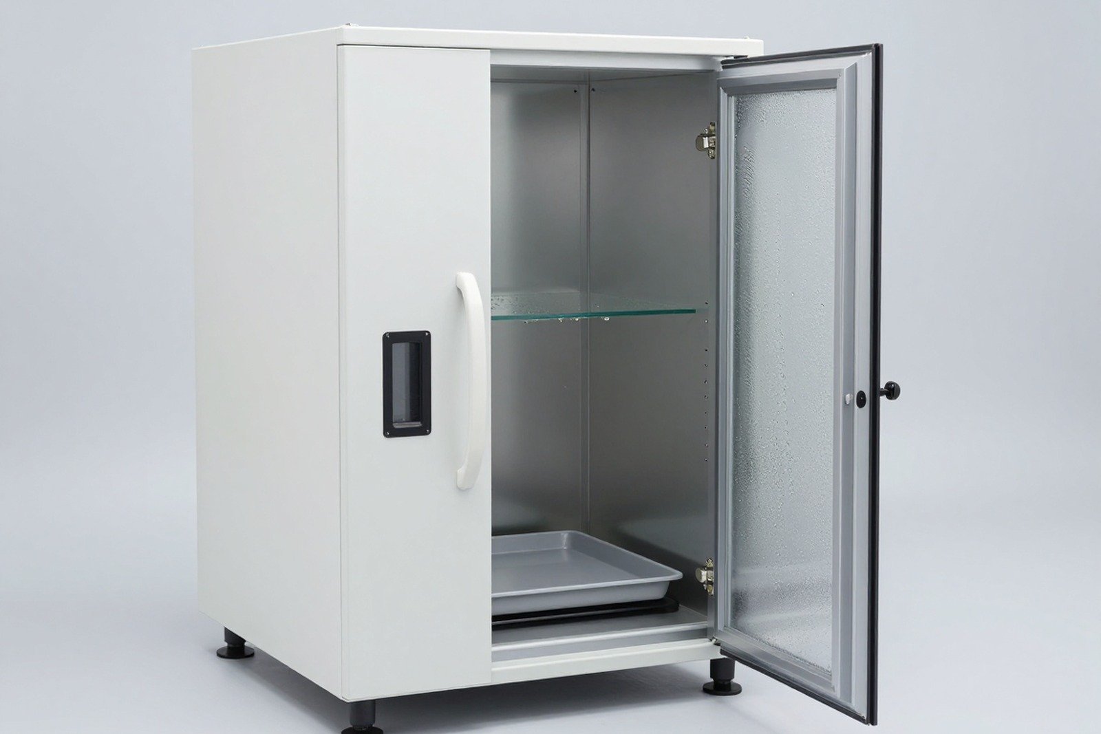
Cover image of the article «Moisture condensation when the sample leaves the cold chamber: causes and ways to control»

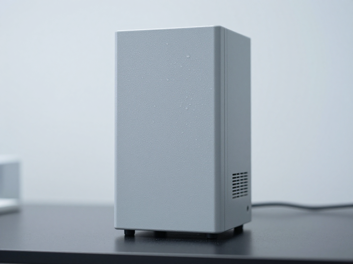
A sample has just come out of the cold chamber and is placed in a test room with air conditioning at 25 °C and high humidity — the sample surface immediately becomes watery. If the technician tests the function at that moment, the measurement result may be “fail” while the product is completely normal.

This article explains the mechanism of moisture condensation after sample removal from the cold chamber, why this is a source of spurious errors, and how to control it in the test room process.

1. Occurring phenomena and conditions

Condensation occurs when the sample surface temperature is lower dew point temperature of surrounding air. When the sample just leaves the cold chamber, the sample surface is colder than the room air; Moisture in the air when it meets a cold surface will condense into water.

Factors that determine the degree of condensation:

  • Temperature difference between the sample and the surrounding environment — the larger it is, the easier it is to condense.
  • Room air humidity — high humidity causes high dew point temperatures close to room temperature.
  • Thermal mass of the sample — large, metal-rich samples stay cold longer, condensing more and lasting longer.
  • Air speed in the room — wind enhances heat and moisture exchange, which can cause condensation to be faster and more even.

In Vietnam, test rooms typically have temperatures of 22–25 °C but seasonally high humidity; This is a very favorable condition for condensation when the sample leaves the cold chamber.

2. Why does moisture condensation cause erroneous results?

Consequences Mechanism Shown in test results
Reduce insulation resistance The water membrane creates a path between points of different potential Insulation measurement “fails”, leakage current increases — but disappears after drying
Fake function error Water bridges the contact, causing a temporary short circuit The device does not start or reports an error immediately after testing
Corrosion onset Moisture film on metal surface, exposed to air Stains and rust appear on details that should not be rusted
Measuring device error Steam condenses on the probe, on the measuring circuit Abnormal measurements, not reproducible when measured again later
Confused about the origin of damage No distinction between damage caused by testing and damage caused by manipulation The conclusion is “sample failed” while the cause is the chamber entry/exit process
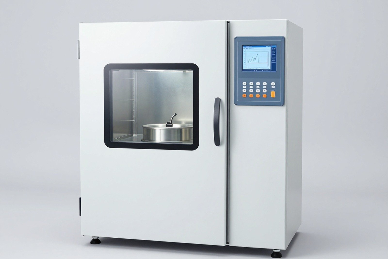
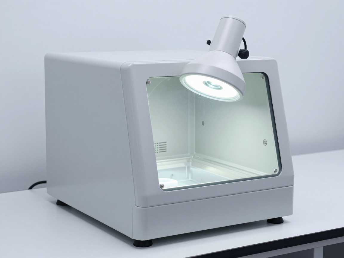
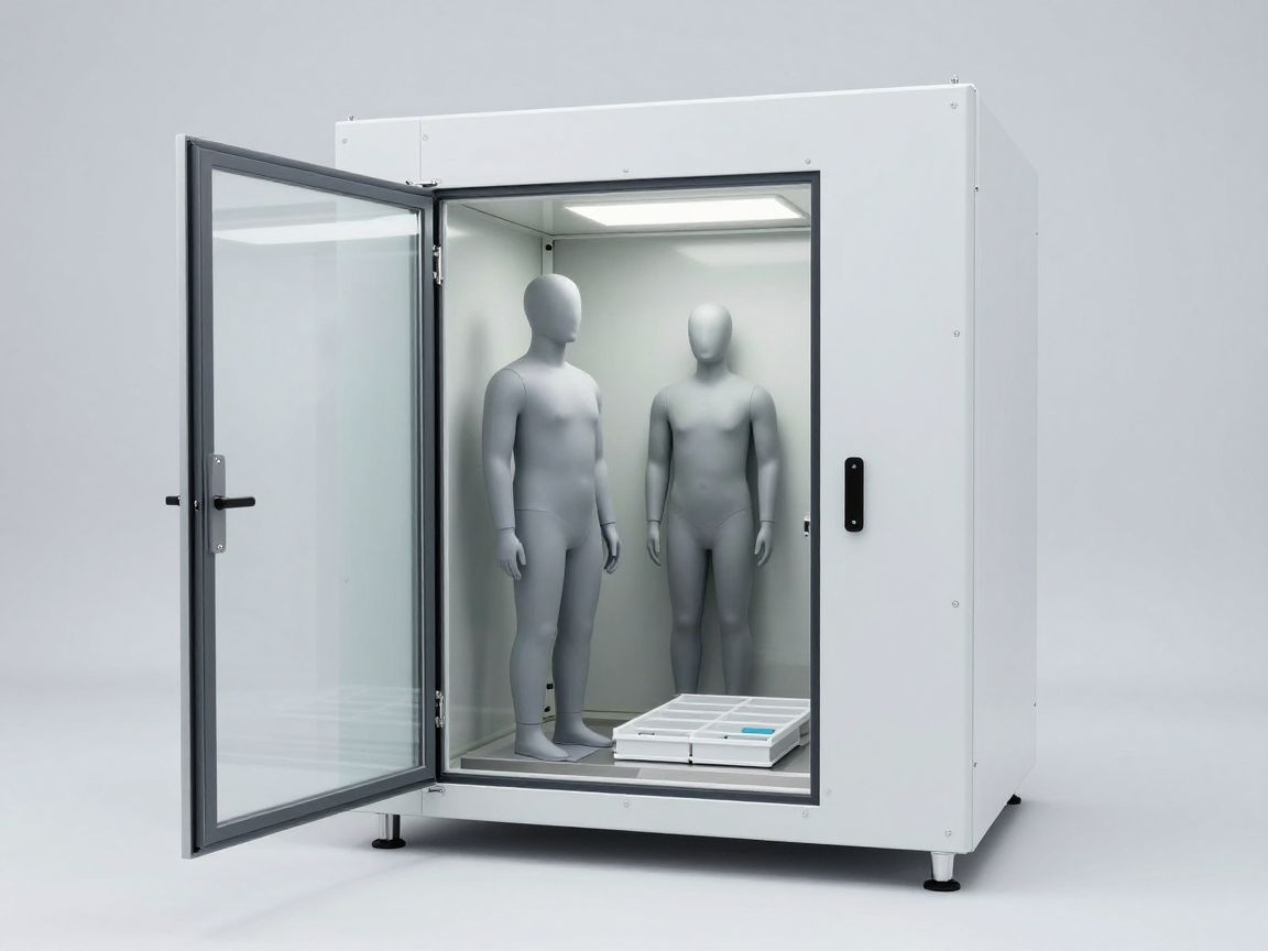
Low temperature test chamber with sample prepared for transfer out
The moment the sample leaves the cold chamber is the time when condensation and false errors are most likely to occur.

3. Distinguish between two sources of condensation

Case Nature How to handle
Condensation in cyclic hot-humidity test As part of the test definition (condensation phase) Follow standards; Record the correct stage
Condensation occurs when the sample leaves the cold chamber Due to operation and room conditions, not part of the test Controlled by recovery process; must not be allowed to influence the conclusion
Condensation when transferring samples between two chambers Due to the intermediate environment, the continuity of the test may be destroyed Use sample transfer boxes/bags or controlled intermediate rooms

This distinction is important: if condensation is part of the test, a “fail” result may be the correct result to record. If condensation is due to manipulation, the result is a spurious error and should not be used as a conclusion.

4. How to control the procedure

  1. Determine recovery conditions as required: Many tests specify conditions and recovery times before testing.
  2. Use a sealed box or bag when transferring samples: Keep the sample in a sealed bag when moving from the cold chamber to the testing area, so that the sample gradually warms up without contact with moist air.
  3. Adaptation time before test: Let the sample reach room temperature before measuring electrical parameters or checking function. If required, measurement at low temperature is not specified.
  4. Check appearance as soon as you leave the room: Taking photos before the water condenses can hide signs of damage.
  5. Dry and gently dry before measuring: Wipe the outer surface with a lint-free material, avoiding blowing moist air directly into the device.
  6. Control room humidity: Maintain an air-conditioned or dehumidified inspection area, especially during the wet season.
  7. Record room conditions: temperature, relative humidity, time the sample was outside the chamber — as evidence of the validity of the results.
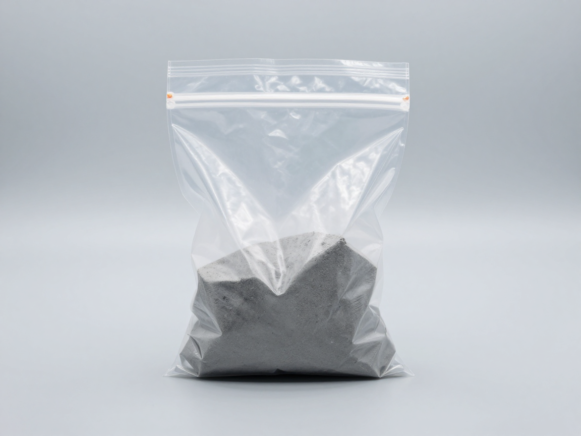
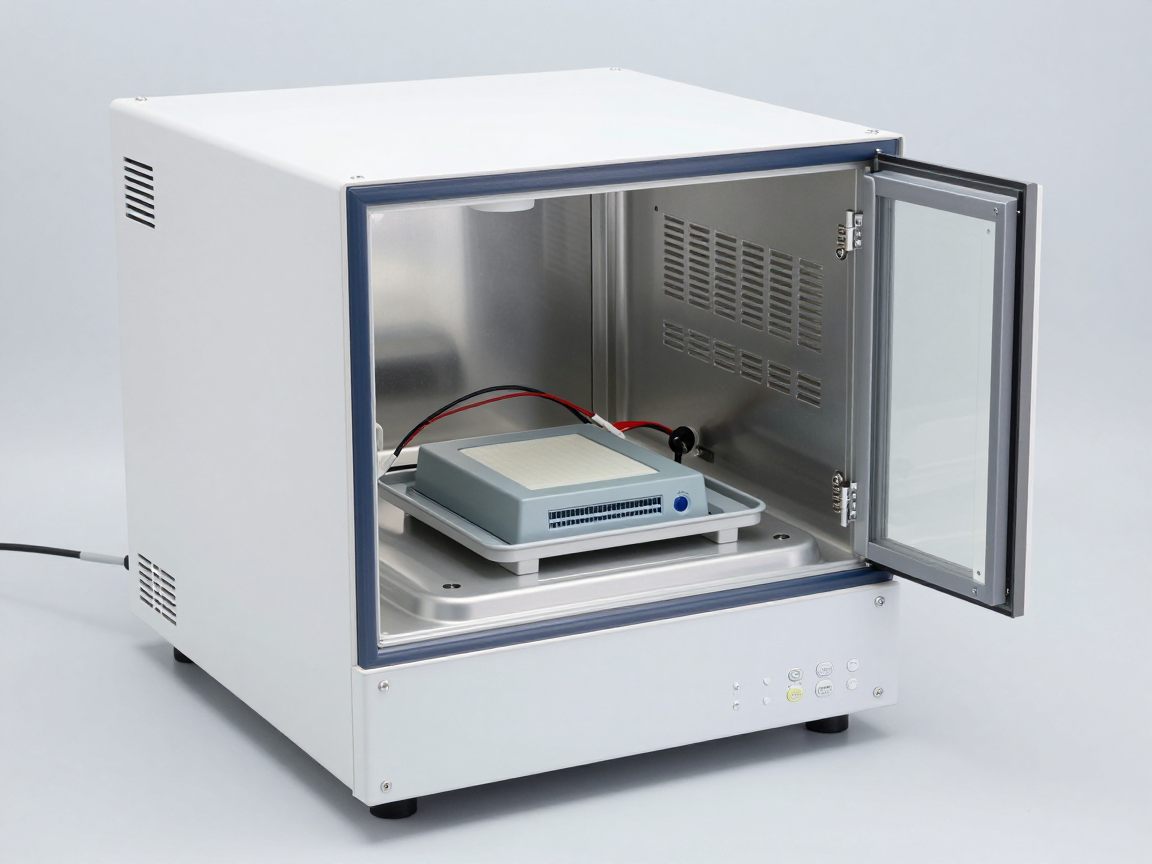
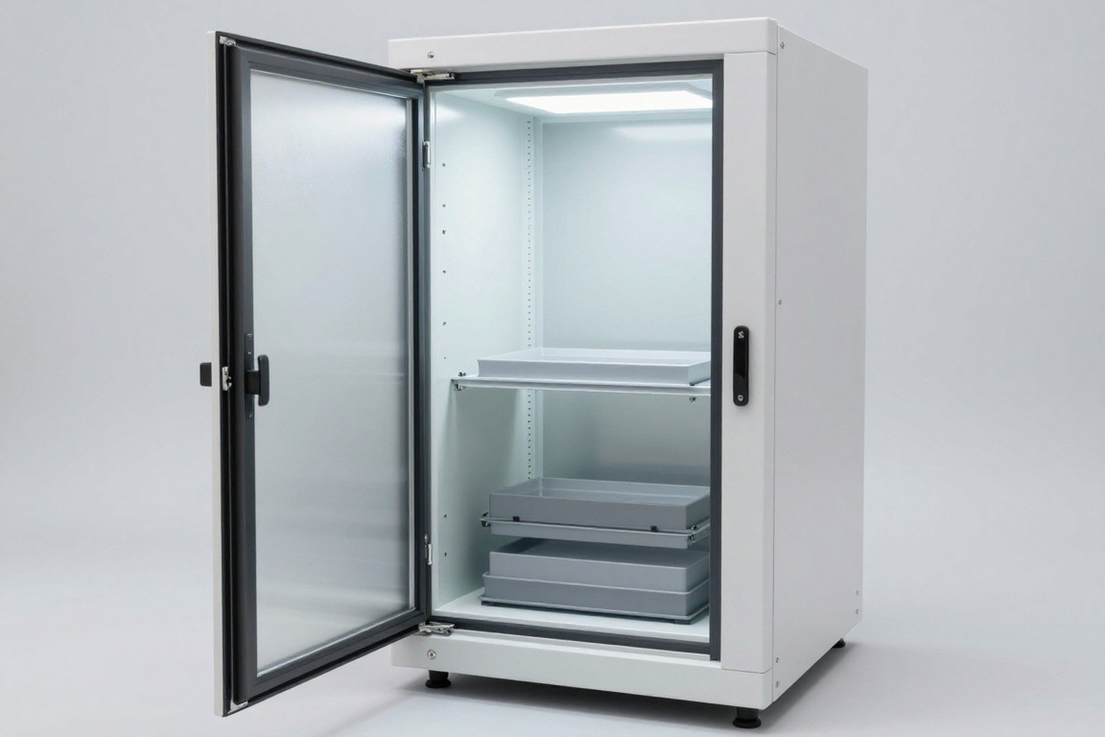
The test sample is placed in a sealed box to be transferred from the cold chamber to the testing area
Transferring samples in sealed containers is the simplest way to prevent unwanted condensation.

5. Points to note when concluding

  • Measure again after drying: If the parameter is abnormal at the first measurement but normal after drying, both measurements and conditions should be recorded.
  • Distinguish between temporary and permanent errors: Faults that appear only at low temperatures may be real faults (e.g. loss of contact due to heat shrinkage); Error due to condensate is a fake error.
  • Do not use measurement results in inappropriate conditions: If measurement is required under standard conditions, measuring when the sample is still cold is the wrong condition.
  • Record photos before and after drying: Let readers of the profile evaluate the level of impact for themselves.

6. Common errors

  • Check function as soon as the sample comes out of the cold chamber while requiring post-recovery testing regulations.
  • Test room conditions are not recorded. leading to unexplained abnormal results.
  • Dry with damp compressed air, causing water to be pushed deep into the device.
  • Consider condensation caused by handling as product damage — the conclusion is wrong and may cause damage to the manufacturer.
  • Skip the visual inspection immediately after leaving the room, loss of evidence of the true condition of the sample.
  • There are no written procedures for entering/exiting the chamber, make each technician do it differently.
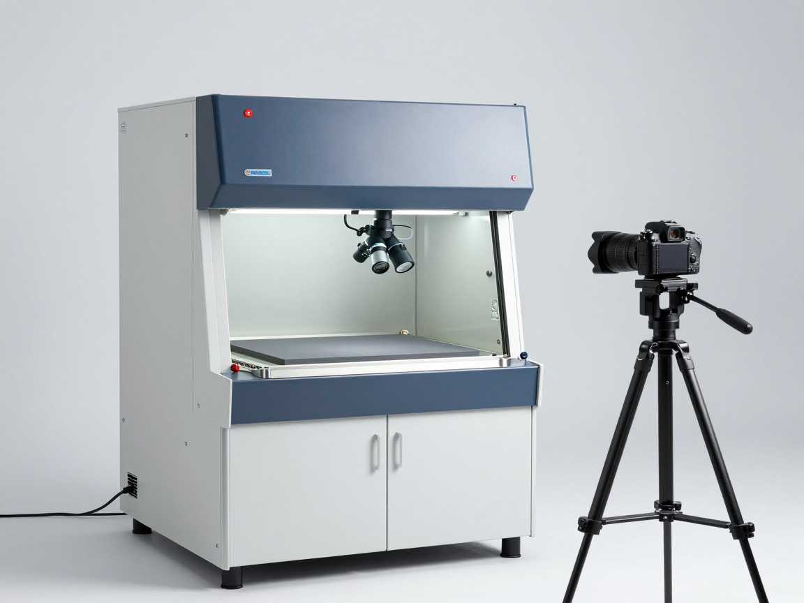
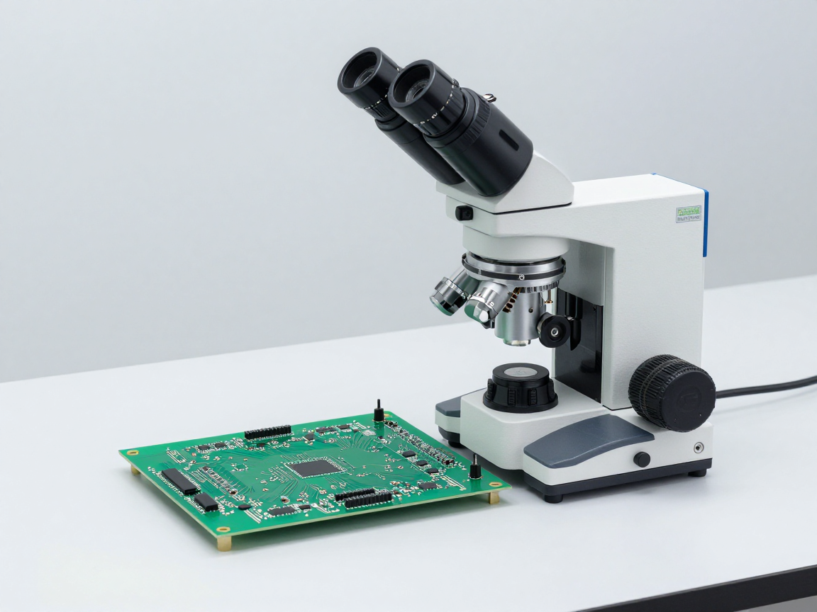
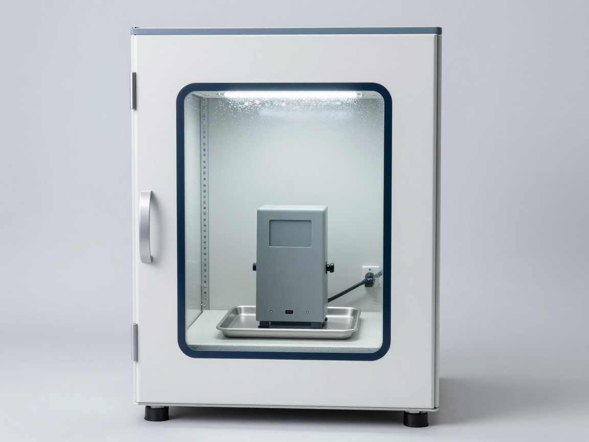
Technician checks the sample after leaving the low temperature test chamber
Checking the appearance immediately after leaving the chamber and recording photos is a way to distinguish real damage from condensation caused by manipulation.

7. Frequently asked questions

Does moisture condensation behind the cold chamber damage the actual product?

In many cases, this phenomenon is only temporary and goes away when it dries. But if the sample has metal surfaces or exposed joints, repeated condensation can initiate corrosion.

How long is enough adaptation time?

Depends on the thermal mass of the sample and the temperature difference. The way to determine for sure is to measure the sample temperature and wait until the sample is close to room temperature, or according to the test’s regulations.

Can I use a dryer to quickly warm the sample?

It is not recommended, as rapid warming creates thermal shock which is not part of the test and may cause new damage. The correct way is to let the sample adapt slowly under controlled conditions.

What if the test requires measuring at low temperatures?

On request, measurements are performed in the chamber or immediately upon sample removal within a limited time. It is necessary to comply with regulations and clearly state the measuring conditions.

How to distinguish errors due to condensation and errors due to low temperature?

Record the phenomenon in two states (wet and dry) and two temperatures (low and room). If the error disappears when dry and at room temperature, it is most likely due to condensation.

Is it necessary to include this content in internal instructions?

There should be. This type of operational error is frequently encountered in climate test rooms in the humid tropics, and it directly affects the reliability of the results.

8. Conclusion

Moisture condensation when the sample leaves the cold chamber is a normal physical phenomenon, but how it is handled determines whether the test results are valid or not. This is the source of many “fail” conclusions that are not true to the actual product.

Three things to do: have a written procedure for transferring samples into/out of the chamber; Transfer samples in sealed bags and adapt samples before testing; and clearly distinguish whether condensation is part of the test or an operational error before drawing conclusions.

References

  • IEC 60068-2-1, 2-2, 2-14 — Cold, dry heat and temperature change tests.
  • IEC 60068-2-30, 2-78 — Cyclic and steady heat testing (test with condensation period).
  • IEC 60068-1 — General regulations and guidance, including recovery conditions.
  • IEC 60068-3-4 — Guidance on humidity testing.
  • ISO/IEC 17025 — General requirements for laboratory competence.

Related articles


Discuss further


    Disclaimer

    This article is an interpretive content compiled by us; not legal advice. Enterprises need to compare relevant documents/standards verbatim before applying them to specific products.

    See more: Copyright Policy & Disclaimer by ticforall.com.
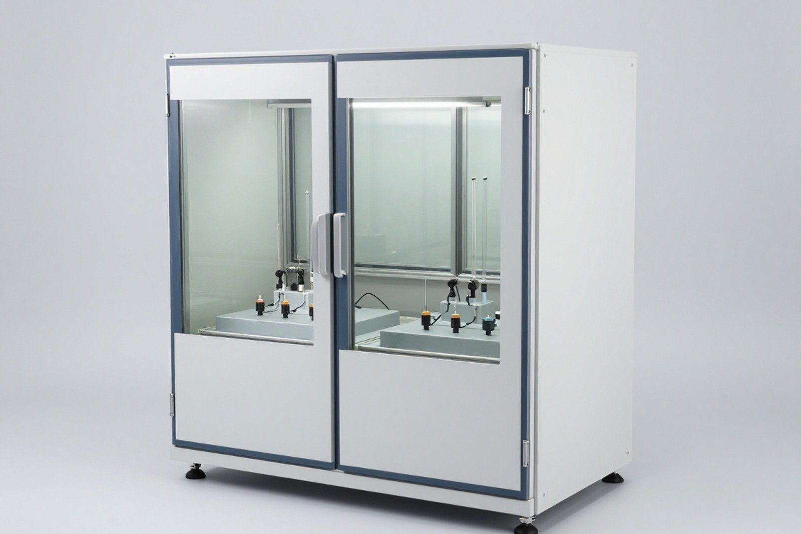
    Load cold/hot test: how to place the sensor and measure sample temperature according to IEC 60068-3-7

    0
    Cover image of the article «Load cold/hot test: how to place the sensor and measure sample temperature according to IEC 60068-3-7»

    A common technical error in temperature testing: reading the temperature on the chamber screen, concluding that the sample has been subjected to the correct conditions, while the actual temperature of the sample is still on track to the required level — or has exceeded the required level due to the device self-heating when energized.

    This article presents the principles of temperature measurement on samples in a loaded chamber, according to the guidance of IEC 60068-3-7, along with the points that must be recorded.

    1. Why is chamber temperature not sample temperature?

    Three reasons:

    • Thermal inertia of the sample: Massive samples need time for the internal temperature to reach the ambient level. The chamber can reach level in just a few minutes while the sample takes tens of minutes or longer.
    • Self-heating: The device being powered generates heat, creating a difference between the sample temperature and the chamber temperature.
    • Local difference: In a large chamber, the temperature is not uniform; The same chamber can have colder and hotter locations.

    Corollary: any conclusion about “the sample was subjected to condition X for time T” requires temperature data on the sample, not data set to the temperature of the chamber.

    2. What does IEC 60068-3-7 instruct?

    This part of the standard provides guidance on measuring temperature in a loaded temperature chamber — that is, when the chamber contains a test sample or simulated load. Core content related to:

    1. How to arrange temperature measurements to accurately reflect the conditions to which the sample is subjected.
    2. Effect of load (sample) on temperature distribution in the chamber.
    3. Principle for determining when the sample reaches the required temperature condition.

    In other words: 60068-3-7 is a document so that temperature testing does not become “environmental measurement, sample conclusion”.

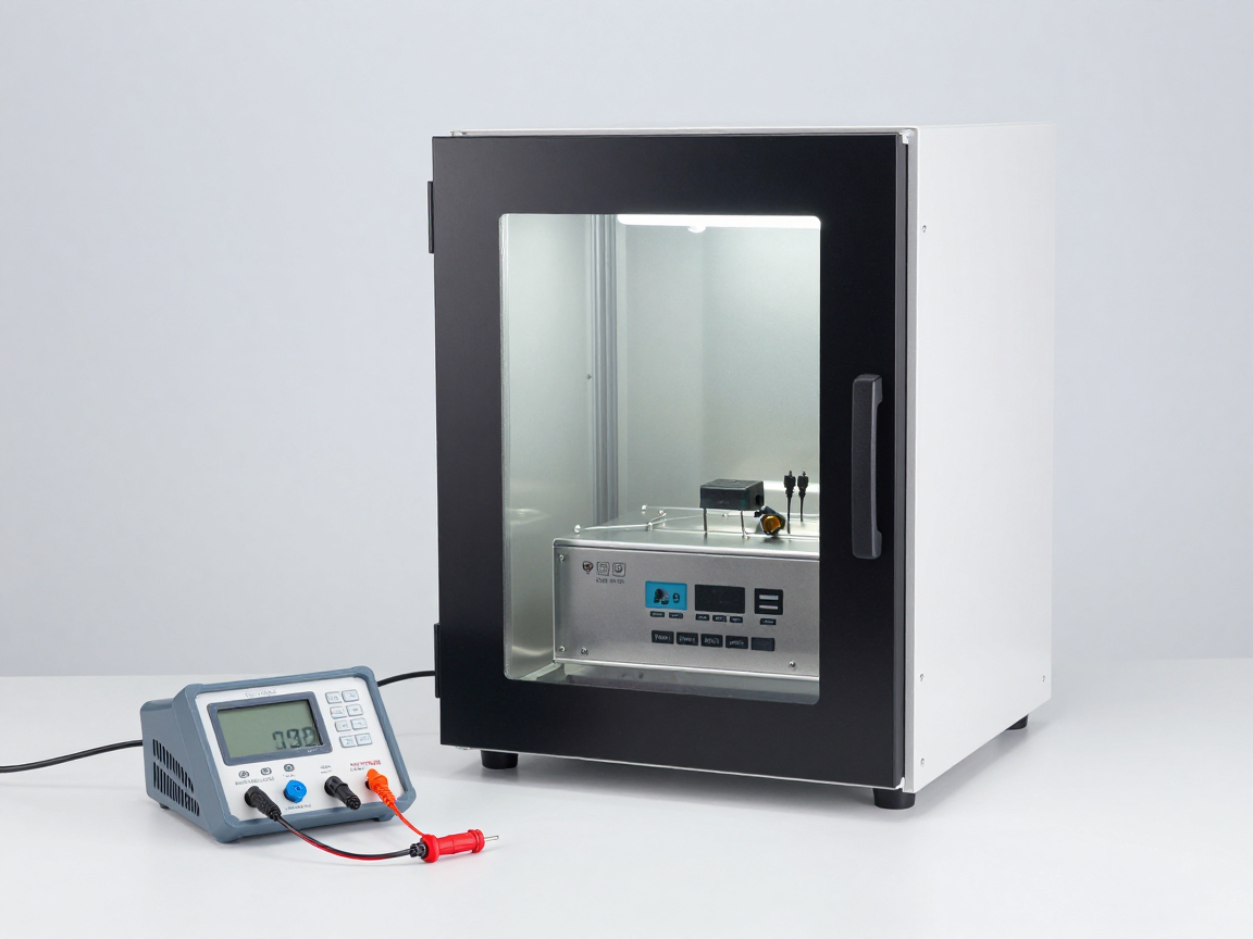
    Temperature chamber with many sensors located at different locations
    With large samples, the sample temperature often lags the chamber temperature significantly.

    3. Principle of placing the temperature sensor on the sample

    Principle How to do it Why?
    Place in a representative position Choose a characteristic thermal point: near a heat-generating component, at a block with a large mass, at a location that is slowest to reach temperature The slowest point determines the time needed to reach equilibrium
    Attach firmly to the sample Fix the sensor, ensuring good thermal contact A separate sensor or poor contact will measure the air temperature, not the sample
    Isolated from chamber walls Do not let the sensor or wires touch the walls of the chamber Avoid measuring chamber surface temperature instead of sample temperature
    Use multiple sensors as needed At least one sensor at a representative point; Add sensors at suspicious points Detection of thermal gradients in samples
    Record location Draw a map of the sensor location and keep it on file Ensure results are reproducible

    4. Self-heating and simulated load

    When the device is tested in the energized state, the actual temperature of the sample may be higher than the chamber temperature. Needs to be handled in one of two directions, depending on the goal:

    • Compensation: Set the chamber temperature so that the temperature at a representative point on the sample reaches the required level. This method simulates the conditions of use but requires measurement on the sample.
    • Try without power: Evaluate viability, eliminating the effects of self-heating.

    For testing on inactive samples but needing to simulate heat load (for example, a cluster with many components), some test laboratories use it download simulation — the part has mass and heat distribution similar to the real sample. When using simulated loads, the characteristics of the load and the reason for use must be clearly stated, because the results do not evaluate the functionality of the real product.

    Sensor placement/load handling error Consequences
    The sensor is placed in the chamber atmosphere, not attached to the sample Reporting that the sample meets the conditions when in reality they do not — the conclusion is too optimistic
    The sensor is mounted in the position where it is most likely to reach heat The holding time is not enough for other areas of the sample
    The sensor touches the wall of the chamber or metal tray Measure device surface temperature, not sample
    Self-heating is not included The sample is subjected to temperatures higher than required, which may cause damage under improper conditions
    No sensor location recorded The results cannot be reproduced in the next attempt
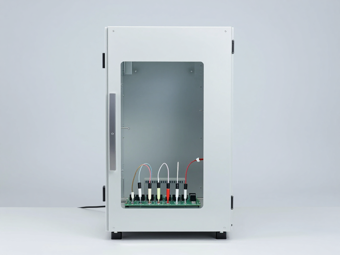
    Thermal sensor mounted on electronic model with fixed leads
    The sensor must be attached to the sample, at a representative point — this is the difference between evidential testing and formal testing.

    5. Determine maintenance time

    The holding time must be sufficient for the sample to reach thermal equilibrium, not just for the chamber to reach set temperature. How to determine reality:

    1. Place the sensor at representative point(s) on the sample.
    2. Monitor sample temperature throughout the thermal transfer process.
    3. Determine when the sample temperature stabilizes within the allowable range.
    4. Start calculating maintenance time from that point (or as specified by the request).
    5. Record the entire temperature curve as evidence.

    With large samples or multi-metal clusters, the time difference can be large. This is also the basis for selecting equipment and planning time for the testing room.

    6. Documents to record

    Section Content
    Sensor location diagram Location on sample, number of sensors, sensor type
    Temperature data over time Chamber temperature and sample temperature, recording frequency
    Load characteristics Power supply status, capacity, simulated load if available
    Confirm chamber capacity Results confirm temperature uniformity, with and without load
    Maintenance time How to determine, start and end time

    7. Common errors

    • Record only the chamber’s set temperature In the report, there is no sample temperature data.
    • Do not confirm chamber capacity under load, leading to unreliable temperature uniformity.
    • Place the sensor in a convenient location instead of representative positions.
    • Ignore spontaneous heating with active equipment.
    • The sensor type and mounting method are not recorded. reduces ability to respond.
    • Use the same measurement point for multiple samples while the samples are in different positions in the chamber.
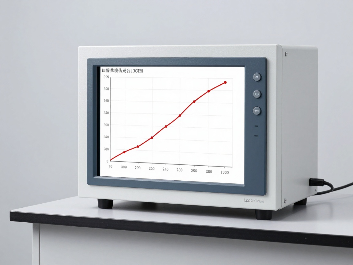
    Graph of chamber temperature and sample temperature over time
    The delay between chamber temperature and sample temperature is the reason for measuring on the sample.

    8. Frequently asked questions

    Is it mandatory to measure the temperature on the sample?

    To draw firm conclusions about the conditions to which the sample is subjected, this data is needed. With small samples and low thermal mass, the difference may be small; but with large samples or powered equipment, omitting this measurement often leads to erroneous conclusions.

    How many sensors is enough?

    Minimum one sensor at representative point. Sensors should be added at points where thermal gradients are suspected or at main heat-generating components.

    How to prove that the sample has reached thermal equilibrium?

    Monitor temperature at representative point; When the temperature changes within the allowable range within a specified period of time, the sample is considered to have reached thermal equilibrium.

    Can simulated loads be used instead of real samples?

    Only for chamber capacity validation purposes or when real samples cannot be used. Results with simulated loads do not replace test results on real products.

    How to handle sample temperature exceeding the required level?

    Record the phenomenon, determine the cause (self-heating, chamber control error, mounting error), and evaluate the impact on the validity of the test. If the condition is false, the test must be repeated.

    Where should I start if the test room does not have a measurement procedure?

    From confirming the capacity of the loaded chamber, then building a process for placing sensors, recording data and determining retention time according to the characteristics of each type of sample.

    9. Conclusion

    Measuring sample temperature is the step that turns a temperature test from an “equipment operation” into a “technical proof”. Chamber temperature is the input condition; The sample temperature is the condition to which the product is actually subjected.

    Three things to do: place the sensor at a representative point and record the position; saves temperature data over time for both chamber and sample; and include self-heating when testing electrically powered equipment.

    References

    • IEC 60068-3-7 — Guidance for measurements in loaded temperature chambers.
    • IEC 60068-3-5 and 60068-3-6 — Validation of temperature chamber and heat-humidity chamber capabilities.
    • IEC 60068-3-11 — Uncertainty of climatic conditions in the test chamber.
    • IEC 60068-2-1, 2-2, 2-14 — Temperature tests.
    • ISO/IEC 17025 — General requirements for testing and calibration laboratory competence.

    Related articles


    Discuss further


      Disclaimer

      This article is an interpretive content compiled by us; not legal advice. Enterprises need to compare relevant documents/standards verbatim before applying them to specific products.

      See more: Copyright Policy & Disclaimer by ticforall.com.
      How are thermal shock and temperature change different? How to choose the right test

      0
      Cover image of the article «How are thermal shock and temperature change different? How to choose the right test»

      The terms “thermal shock” and “change of temperature / thermal cycling” are often used interchangeably in technical discussions. But they describe two different failure mechanisms, leading to two different testing approaches.

      This article differentiates the two concepts, explains when one is needed, and the errors when using one to conclude the other.

      1. Why are these two concepts often used interchangeably?

      Because both are related to temperature changes between two levels. The difference is not in temperature, but in heat transfer rate, number of cycles, and damage mechanism targeted by the test:

      • Thermal shock: Pay attention to the instantaneous stress when the sample transfers heat very quickly. Damage can appear after just a few cycles.
      • Temperature change/thermal cycling: Pay attention to fatigue accumulated over many cycles with moderate heat transfer rates. Damage appears after a significant number of cycles.

      2. Distinguishing table

      Aspect Thermal shock Temperature changes/thermal cycling
      Question answered Can the product withstand sudden changes in temperature? Does the product withstand cumulative thermal fatigue?
      Heat transfer rate Very quickly, samples are often immediately transferred between two environments Controlled, at a prescribed speed
      Typical number of cycles Few (a few cycles to a few dozen) Many (hundreds to thousands, depending on requirements)
      Main failure mechanism Cracks due to thermal stress, breakage of brittle materials, peeling of coatings, opening of joints Weld fatigue, material fatigue, parameter drift, loss of seal
      Test time Shorter if the number of cycles is small Longer, depends on the number of cycles
      Device requirements Rapid sample transfer system or two chambers The chamber has precise ramp control
      Two temperature test chambers with sample transfer system for thermal shock testing
      Thermal shock is often achieved by rapidly transferring samples between two chambers or between two environments.

      3. Corresponding tests in each standard system

      Standard system Related tests Notes
      IEC 60068-2-14 Na (rapid temperature change), Nb (slow temperature change) Na with a fast heat transfer rate is often used for thermal shock purposes
      MIL-STD-810 Thermal shock test method Philosophy of level selection according to life cycle environment
      Semiconductor component industry standards (JESD family) Thermal cycling for components Multiple cycles, fatigue goals and component reliability
      Electronic assembly industry standards (IPC family) Thermal cycle for solder joints and circuit boards Associated with thermal cycle weld fatigue assessment

      Important note: symbols and how to determine severity levels vary between systems. Results should not be extrapolated from one system to another without a recognized reference table.

      4. Choosing the right test for the objective

      Target Appropriate test Reason
      Assess the risk of cracking due to sudden temperature changes during transportation and storage Thermal shock (Na at a rapid rate) Simulates extreme conditions instantaneously
      Evaluate weld life and material fatigue according to usage life cycle Thermal cycle (Nb or equivalent) Evaluate cumulative fatigue by number of cycles
      Screening for manufacturing defects Thermal shock has a low number of cycles Quickly detect defective assembly parts
      Prove the design meets customer requirements According to the standards cited by customers Avoid trying to be correct but not meeting the requirements

      5. Why does the rate of heat transfer determine the result?

      For samples with large thermal mass, the surface temperature and core temperature are never equal during the heat transfer stage. This difference creates internal stress. The faster the heat transfer, the larger the difference and the higher the stress.

      Practical consequences:

      • Same temperature range, tested at a faster speed gives harsher results — but not technically equivalent.
      • Large samples may not pass thermal shock but pass thermal cycling (or vice versa), because the two tests target two different mechanisms.
      • The rate of change in temperature of the air in the chamber is not equal to the rate of change in temperature of the sample. Need to measure on sample.
      Thermal sensor mounted on the sample and temperature data logger
      It is necessary to measure the temperature on the sample, because the chamber temperature is not representative of the rate of thermal change of the sample.

      6. Mistakes when using one test instead of another

      • Using thermal shock to conclude about thermal fatigue: The number of cycles is too small, not enough to reveal accumulated fatigue.
      • Using slow speed thermal cycling to draw conclusions about thermal shock tolerance: Low speeds do not create equivalent instantaneous stresses.
      • No heat transfer rate recorded but only records two temperatures — results are not reproducible.
      • Do not record the number of cycles and intermediate inspection cycles — the level of fatigue is unknown.
      • Do not measure temperature on the sample — does not prove that the sample is actually subjected to the stated conditions.
      • Apply the results of this standard system to the requirements of another standard system when there is no comparison.
      Graph of temperature over time comparing fast and slow heat transfer rates
      The heat transfer rate is the decisive parameter: same amplitude but different speed for two essentially different tests.

      7. Frequently asked questions

      Is thermal shock more severe than temperature change?

      Cannot be compared directly because they target two different mechanisms. Thermal shock is more severe in terms of instantaneous stress; Thermal cycles are more severe in terms of cumulative fatigue.

      How many cycles are considered thermal shock?

      There is no distinct cycle count threshold. The distinguishing criteria are the heat transfer rate and the damage mechanism to be evaluated.

      What if the customer only writes “thermal shock”?

      Customers are requested to confirm specific standards, two temperature levels, holding time, sample transfer time and number of cycles. These are required parameters for this to work.

      Can the same chamber be used for both tests?

      Yes if the chamber meets the required rate of temperature change. With high-speed thermal shock, a two-chamber system or specialized sample transfer system is often needed.

      Where should functional testing be located?

      At intermediate milestones as required, and after completion. For products with safety functions, continuous monitoring during the heat transfer phase is recommended.

      Does thermal shock detect weld errors?

      Yes, especially with poor quality welds or defective joints. But with life cycle weld fatigue, multiple heat cycles are more suitable.

      What standards should electronic circuit boards follow?

      Depending on requirements: can follow IEC 60068-2-14 if the customer cites this set, or according to electronics assembly industry standards when life cycle weld fatigue assessment is required. It is important to agree in advance on the test, the number of cycles and the passing criteria.

      If the sample has a large volume, which method should I choose?

      Need to consider: large volumes make it difficult to achieve fast heat transfer rates, so thermal shock may not meet the required conditions. In that case, measure the temperature on the sample to confirm the actual speed before jumping to conclusions.

      8. Conclusion

      Thermal shock and temperature change are two essentially different tests, distinguished by heat transfer rate, number of cycles and damage mechanism to be evaluated. Using one rule to rule out another is a common source of erroneous conclusions in confidence profiles.

      Three things to do: determine assessment goals before choosing the test method; Record all five parameters (two temperature levels, heat transfer rate, retention time, number of cycles, sample status); and measure the temperature on the sample to prove the test performed as described.

      References

      • IEC 60068-2-14 — N test: Temperature change (Na and Nb).
      • IEC 60068-1 — General provisions and guidance.
      • IEC 60068-3-7 — Measurement in loaded temperature chamber.
      • MIL-STD-810 — Environmental test methods (temperature method group).
      • Industry standards for semiconductor components and electronic assemblies (JESD family, IPC family).

      Related articles


      Discuss further


        Disclaimer

        This article is an interpretive content compiled by us; not legal advice. Enterprises need to compare relevant documents/standards verbatim before applying them to specific products.

        See more: Copyright Policy & Disclaimer by ticforall.com.
        N test: temperature change according to IEC 60068-2-14 (Na, Nb)

        0
        Cover image of the article «N test: temperature change according to IEC 60068-2-14 (Na, Nb)»

        Tests A (cold) and B (dry heat) hold the product in place one temperature. The N test is different: it evaluates what happens to the temperature change — and this is the factor that causes damage to welds, joining materials and structures in reality.

        This article explains N testing according to IEC 60068-2-14, the difference between Na and Nb, the parameters that must be recorded, and the failure mechanisms to observe.

        1. What question does Test N answer?

        The N (Change of temperature) test evaluates the effect of repeated temperature changes between two levels. Specific question:

        • Can the product withstand the stresses of expansion and contraction that vary between materials?
        • Are welds, joints, or coatings cracked or exposed after many cycles?
        • Does the structure jam or lose contact when the temperature changes?
        • Do electrical parameters drift with thermal cycling?

        The core difference compared to A/B Testing: failures here come from number of cycles and rate of temperature change, not just from the absolute temperature value.

        2. What is the difference between Na and Nb?

        Characteristics Na Nb
        Rate of temperature change Fast — used when sudden temperature changes need to be simulated Slow, controlled speed — simulates gradual heat changes
        Evaluation goals Thermal stress and thermal shock on joints and materials Thermal fatigue accumulates, changing the material state
        Severity level Higher with the same temperature amplitude Lower, but usually lasts more cycles
        Device requirements Need rapid heat transfer capability, which may require two chambers or sample transfer systems The chamber has ramp speed control

        Consequence: Na results cannot be used to conclude Nb requirements and vice versa. With the same temperature range, Na is significantly harsher in speed.

        The temperature test chamber has a temperature change rate control
        With N testing, the rate of temperature change and the number of cycles are the two parameters that determine the results.

        3. Parameters must be recorded in the request and report

        Parameters Meaning Why is it important?
        Low temperature (TA) and tall (TB) Two temperature levels of the cycle Determine the temperature range — the main factor causing stress
        Time maintained at each level Sample holding time at TA and TB Make sure the sample reaches thermal equilibrium before switching levels
        Rate of temperature change Speed of transition from one level to the other Determine the level of thermal shock and instantaneous stress
        Number of cycles Number of repetitions Determines the ability to detect thermal fatigue
        Sample transfer time With Na, the time it takes the sample to move between the two chambers Direct impact on results
        Sample status Unpowered / powered / with load Guaranteed to reproduce results

        4. Failure mechanism needs to be observed

        Details Mechanism Signs
        SMD solder joints The difference in expansion coefficient between components and circuit boards causes fatigue Cracked solder joints, increased contact resistance, loss of intermittent function
        Through-hole component pins Cyclic tensile-compressive stress Cracks around pins, cracked weld rings
        Coating, paint, glue Different expansion causes flaking Flaking edges, surface cracks, loss of protection
        Connectors, jacks Loss of clearance when temperature changes Flickering contact, increased insertion force
        Glass, screen, clear plastic Local thermal stress Cracked, cracked, blurred
        Gasket, sealed Loss of elasticity after many cycles Leaks, loss of seal, open joints
        Electronic circuit board with solder joints observed under magnification
        With welds, thermal cycling causes cumulative fatigue — damage is usually only seen after many cycles.

        5. Implementation sequence

        1. Initial stabilization and milestone testing: Appearance, functions, electrical parameters.
        2. Sample mount: As specified, record the temperature sensor location on the sample.
        3. Go to the first temperature level, Maintain enough time for the sample to reach thermal equilibrium.
        4. Switch to the second temperature level according to the prescribed speed and time, maintaining enough stabilization time.
        5. Repeat for the specified number of cycles.
        6. Function test: as required, possibly after a number of cycles and after termination.
        7. Recovery, visual inspection and conclusion according to agreed criteria.

        It is often recommended to examine appearance and function at intermediate points (e.g. after a fraction of cycles) to determine trends in deterioration rather than just final results.

        6. Factors that determine test results

        • Thermal mass of sample: determines the rate at which the actual temperature of the sample changes, as opposed to the rate at which the air temperature in the chamber changes.
        • Sensor location: Place it in a representative location for heat, not in a favorable location.
        • Self-heating when power is applied: causing the actual temperature of the sample to deviate from the chamber temperature.
        • How to mount: The holder can create a thermal path that patterns abnormally fast/slow thermal changes.
        • Sample transfer time (with Na): If it is longer than specified, the test is no longer valid.

        7. Common errors

        • Write “temperature change test” without writing Na/Nb and does not state the number of cycles — records cannot be compared.
        • Conclusion according to chamber temperature without measuring sample temperature.
        • Do not wait for the sample to reach thermal equilibrium at each level before moving to the other level.
        • Mistaking the chamber ramp rate for the sample’s temperature change rate.
        • Not checking intermediate landmarks, leading to not knowing at what cycle the product fails.
        • Use Test N to replace Test A/B when the objective is to evaluate the ability to withstand prolonged stable temperatures.
        Graph of temperature over time of temperature change cycle
        Recording temperature data over time helps prove that the test is at the correct speed, the correct number of cycles, and that the sample has reached thermal equilibrium.

        8. Frequently asked questions

        Is the N test “thermal shock”?

        Not entirely consistent in terminology. Na with a fast heat transfer rate is often used for thermal shock purposes. See the article on how thermal shock and temperature change are different to clearly differentiate.

        How many cycles is enough?

        As required or industry standard, based on assessment objective (screening, fatigue assessment, or life cycle simulation). There is no general number.

        Should I choose Na or Nb when there are no specific requirements?

        Choose according to the goal: if you want to evaluate the ability to withstand sudden temperature changes, then Na; If you want to simulate a life cycle with slowly changing temperature, then Nb. Should agree with the customer in writing.

        Does the N test require two chambers?

        Not required. This can be done by transferring the sample between two chambers or by using a chamber capable of rapid temperature changes. It is important to achieve the required rate of heat change.

        Does a powered model require continuous functional monitoring?

        Depends on the goal. With safety devices or devices with intermittent faults, continuous monitoring is recommended as the fault may only appear during the heat transfer phase.

        After test N, do I have to try any other tests?

        Usually yes. In many series, Test N is preceded by vibration/shock so that potential joint failures are exposed when subjected to mechanical loading.

        9. Conclusion

        The N test is a test of cyclic stress, not of extreme temperature. The value of the result depends on the correct recording of variation (Na/Nb), temperature amplitude, rate of change, retention time and number of cycles.

        Three things to do: measure the temperature at a representative point on the sample to prove thermal balance is reached; records temperature data over time for the entire cycle; and check the intermediate mark for a decreasing trend.

        References

        • IEC 60068-2-14 — Test N: Change of temperature, including Na and Nb.
        • IEC 60068-1 — General provisions and guidance.
        • IEC 60068-3-7 — Measurement in loaded temperature chamber.
        • IEC 60068-3-5 — Confirmation of temperature chamber capacity.
        • TCVN 7699-2-14 — Corresponding national version.

        Related articles


        Discuss further


          Disclaimer

          This article is an interpretive content compiled by us; not legal advice. Enterprises need to compare relevant documents/standards verbatim before applying them to specific products.

          See more: Copyright Policy & Disclaimer by ticforall.com.
          Test B (Dry heat): dry heat test according to IEC 60068-2-2, Bb and Bd

          0
          Cover image of the article «Test B (Dry heat): dry heat test according to IEC 60068-2-2, Bb and Bd»

          Dry heat test according to IEC 60068-2-2 is a “brother” test to cold test: same group of temperature agents, same two variants Bb and Bd, but completely different damage mechanism. The most common misconception is that the dry heat test can replace the moist heat test.

          This article explains the dry heat test, the difference between Bb and Bd, the failure mechanisms to observe, and what must be documented.

          1. What question does Test B answer?

          The dry heat test evaluates the product’s ability to operate and/or survive high temperatures in the absence of additional moisture. Specific question:

          • Does the product function properly at high temperatures?
          • Are plastic materials, glue, and gaskets deformed, soft, or aging quickly?
          • Do lubricants, inks, and labels evaporate or dry out?
          • Do electrical and electronic components lose parameters when the temperature increases?
          • Is the structure expanding, causing mechanical jamming or loss of contact?

          2. What is the difference between Bb and Bd?

          Characteristics BB Bd
          Main goal Evaluated in a stable hot temperature state Evaluated during heat up and at elevated temperatures, with functional testing during the changeover period
          Time to test functionality After the sample reaches high thermal equilibrium Monitor during temperature rise as prescribed
          Device requirements Dry heat chamber reaches and holds temperature Needs a heat-resistant measuring system and continuous monitoring
          Typical application Hot storage, transportation, equipment operating in hot environments The device starts and operates when the temperature is rising

          Note on terminology: Bb is often associated with the scenario “constant temperature throughout the test, testing at high temperature”, while Bd is associated with the scenario “temperature changes and checking function during the change”. When reading requirements, clearly define the goal before choosing a variation.

          Dry heat test chamber with electronic sample inside
          The dry heat chamber controls temperature but does not add humidity — a key difference from the dry heat test.

          3. Failure mechanism needs to be observed

          Material/detail group Common mechanism Signs to note
          Plastic case Soft, deformed, discolored, brittle after testing Size distortion, warping, surface discoloration
          Glue, gasket, gasket Soft, oily, loss of elasticity Oil leaks, loss of sealing, moving parts
          Lubricant Evaporates, separates oil, dries hard Increased friction, noise, mechanical jamming
          Screens, ink, labels Blurred, flying ink, peeling labels Reduced contrast, peeling label edges
          Batteries, capacitors Parameter drift, reduced lifespan, swelling Reduced capacity, increased leakage current, case swelling
          Welds, contacts Different expansion causes stress and surface oxidation Increased contact resistance, flickering contact
          Mechanical structure Expansion causes jamming and loss of clearance Unable to install, increased operating force, shaft stuck

          4. Implementation sequence

          1. Initial stabilization and milestone testing: Appearance, functions, parameters.
          2. Sample mount: ensure representative heat exchange; Do not mount so that the sample is “cooled” by the metal support.
          3. Increase heat to specified level: at the specified speed if required.
          4. Maintaining at high temperatures: enough time for the sample to reach thermal equilibrium, not just for the chamber to reach temperature.
          5. Function test: according to Bb (after stabilization) or Bd (during heating).
          6. Recovery: according to prescribed conditions and time.
          7. Final test and conclusion: Compare with the original benchmark according to agreed criteria.

          5. Factors that determine test results

          • Self-heating: The device has a self-heating power supply, causing the actual temperature of the sample to be higher than the chamber temperature. This is the point that is most often overlooked.
          • Volume and density of components: Multi-metal clusters take longer to reach thermal equilibrium.
          • Sensor location: mounted at a representative point, recording the location on file.
          • Air circulation in the chamber: affects temperature uniformity and heat transfer rate.
          • Bracket material: Metal racks conduct heat quickly, which can create local “cold spots”.

          The temperature range and holding time are selectable upon request; The standard does not impose a single level. With industrial and electronic equipment, common levels are within the operating and inventory temperature ranges published by the manufacturer — which should be compared with specific requirements documents rather than applied out of habit.

          Temperature data logger and sensor in hot test chamber
          Monitoring the temperature at a representative point proves that the sample has reached thermal equilibrium throughout the holding period.

          6. Dry heat and humid heat: do not replace each other

          This is the most misleading point. Two tests evaluate two different mechanisms:

          Aspect Dry heat (Test B) Hot and humid (Test C, D)
          Main stress factor High temperature, no additional moisture Temperature combined with high humidity
          Typical failure mechanism Material aging, expansion, evaporation, plastic softening Condensation, moisture absorption, insulation breakdown, electrochemical corrosion
          Cannot be substituted for Evaluate insulation breakdown in highly humid environments Evaluation of thermal aging of materials

          7. Common errors

          • Consider dry heat a general “temperature test”. Then use it to draw conclusions for both hot and humid environments.
          • Do not write Bb or Bd — loss of ability to compare results.
          • Self-heat generation is not taken into account of electrically powered equipment.
          • Do not check appearance after testing — miss deformation, discoloration, oil leakage.
          • Conclusion: When there is not enough time for thermal stabilization, distort results with large samples.
          • Skip recovery before functional testing, causing the measuring equipment to fail to meet working conditions.
          Check the appearance of the plastic sample after the dry heat test
          Many damages caused by dry heat are only evident on visual inspection: warping, discoloration, and oil leaks.

          8. Frequently asked questions

          How is hot-dry testing different from testing in a regular oven?

          Different in three points: temperature uniformity is confirmed, there is a regulation on the time to reach thermal equilibrium of the sample, and there are pre-agreed testing criteria.

          What temperature should be chosen?

          Choose according to the usage environment or customer requirements/industry standards, then clearly state the basis. There is no common level for all products.

          Does dry heat testing require power supply for the sample?

          Depends on the goal. Try without power to assess viability; Test with power supply to evaluate operability. If there is power supply, self-heat generation must be taken into account.

          What should you pay attention to if the device has a battery/accumulator?

          High temperatures strongly affect the battery: reducing capacity, swelling, increasing safety risks. It is necessary to separately monitor and consider the safety requirements of industry standards.

          Can the same sample be run for cold testing and dry heat testing?

          It is often possible, if the objective is an existential assessment and the requirements document does not specify a separate template. The order of implementation should be clearly stated in the dossier.

          After the dry heat test, is the plastic discoloration considered unsatisfactory?

          Depends on criteria. If the criteria only require functionality, color change is acceptable; If the product is a retail item, discoloration may be a serious defect. Criteria must clearly state the boundaries.

          9. Conclusion

          The dry heat test is a separate test, not a duplicate of the moist heat test. The value of the results lies in the correct recording of variation (Bb/Bd), temperature level, holding time, sample condition and passing criteria.

          Three things to do: choose the variant according to the target (survival or activity during heating); Monitor the temperature at a representative point to prove that the sample has reached thermal balance; and a thorough visual inspection after testing because many thermal damages do not show up through functional testing.

          References

          • IEC 60068-2-2 — Test B: Dry heat, including Bb and Bd.
          • IEC 60068-1 — General provisions and guidance.
          • IEC 60068-3-1 — Guidelines for cold and dry heat testing.
          • IEC 60068-2-30, 2-78 — Testing for cyclic and stable humidity.
          • TCVN 7699-2-2 — Corresponding national version.

          Related articles


          Discuss further


            Disclaimer

            This article is an interpretive content compiled by us; not legal advice. Enterprises need to compare relevant documents/standards verbatim before applying them to specific products.

            See more: Copyright Policy & Disclaimer by ticforall.com.
            Test A (Cold): cold test according to IEC 60068-2-1, how are Ab and Ae different?

            0
            Cover image of the article «Test A (Cold): cold test according to IEC 60068-2-1, how are Ab and Ae different?»

            Test A (Cold) according to IEC 60068-2-1 is the most basic test in the standard, but also the most mislabeled test: most documents only state “cold test” without mentioning the Ab or Ae variation — while these two variations lead to different implementation and testing methods.

            This article explains the purpose of the cold test, the difference between Ab and Ae, the procedure for performing it, and the factors that determine the test result.

            1. What question does Experiment A answer?

            The cold test evaluates the product’s ability to operate and/or survive at low temperatures. Specific questions include:

            • Does the product still start and operate properly at low temperatures?
            • Does the material crack, become brittle, shrink or lose elasticity?
            • Are lubricants, gaskets, glues, soft materials still functional?
            • Are electrical connections affected when materials shrink at low temperatures?

            Wide range of applications: electrical and electronic equipment, components, assemblies, materials and finished products. This is also a commonly used test to evaluate the ability to withstand transportation and storage in cold climates.

            2. What is the difference between Ab and Ae?

            Characteristics Ab Ae
            Main goal Evaluate the product at completely cooled temperature (thermal stability) Evaluate the product during cooling down and at low temperatures, with functional testing during the changeover period
            Time to test functionality Check after the sample has stabilized temperature, measurement can be done right in the chamber Check during cooling (continuous measurement or at specified time)
            Device requirements Just need the cold chamber to reach and keep the temperature Needs a measuring system that operates at low temperatures and continuously monitors
            Typical application Equipment inventory, transportation, start-up after cooling The device must operate even when the temperature is falling, e.g. outdoor equipment

            Practical consequence: if Ab is required, the results do not demonstrate the behavior of the product during cooling. If Ae recording is required, the results cannot be substituted for a prolonged thermal stability test.

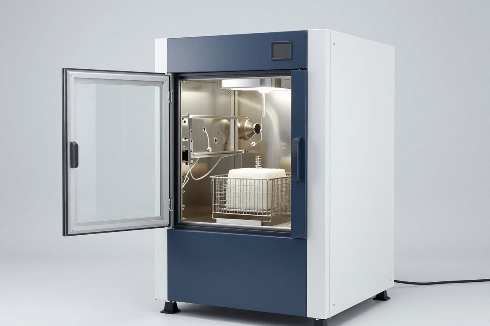
            Low temperature test chamber with test sample inside
            The cold chamber must be qualified before being used for testing according to IEC 60068-2-1.

            3. Procedure for performing a cold test

            1. Initial stability: Bring the sample to standard conditions according to regulations, check appearance and function to establish a benchmark.
            2. Sample mount: Place the sample in the chamber in a manner that simulates usage or regulatory conditions; Avoid mounting that changes the heat exchange ability of the sample.
            3. Heat reduction: Lower the chamber temperature to the specified level. Some requirements specify the rate of cooling; need to be complied with if any.
            4. Maintain: keep the temperature at the specified level for the specified time, enough for the sample to reach thermal equilibrium (not just enough for the chamber to reach temperature).
            5. Function test: carried out according to Ab (after stabilization) or Ae (during cooling), according to agreed criteria.
            6. Recovery: Bring the sample to standard conditions and allow specified recovery time before final inspection.
            7. Conclusion: Compare with the initial milestone according to the set criteria.

            4. Severity and duration

            IEC 60068-2-1 gives a range of temperatures and times to choose from, without imposing a single level. In practice, common levels for industrial and electronic equipment include deep negative values ​​that vary depending on the application — temperate regions, cold regions, cold storage or aerospace applications. The choice of level must come from the usage environment (see article Select the environmental test according to the usage environment) and must be clearly stated in the request.

            Factors to record Why is it important?
            Low level temperature Decide on the severity level and which materials are affected
            Maintenance time Make sure the sample reaches thermal equilibrium, not just the chamber reaches temperature
            Heat reduction rate Effects on thermal stress and results with welds and joining materials
            Sample status To power or not to power; loaded or not
            Time of inspection In the chamber or after recovery; conclusion decision
            Thermal sensors and devices record temperature data over time
            Temperature data over time is evidence that the sample has reached thermal equilibrium during the holding period.

            5. Factors that determine test results

            • Mass and material of sample: Large samples with many metals need longer time to reach thermal equilibrium.
            • Sensor location: The sensor must be mounted in a representative location, not just a convenient location.
            • Self-heating: The device has a self-heating power supply, causing the actual temperature of the sample to be higher than the chamber temperature.
            • How to mount: Metal supports can conduct heat and change the cooling rate of the sample.
            • Chamber tightness and chamber sensor location: affects temperature uniformity.
            • Check appearance before testing: Without pre-test photos, it is not possible to prove that the crack is due to the test.

            6. Common errors

            • Write “cold test” without writing Ab/Ae — the results do not match the requirements.
            • Conclusion as soon as the chamber reaches temperature, not enough time for the sample to reach thermal equilibrium.
            • Do not record the power supply status of the sample — results are not reproducible.
            • Check function after sample has returned to room temperature, Missing errors that only appear at low temperatures.
            • Not checking appearance before and after, leading to disputes about the origin of the damage.
            • Skip recovery, causes moisture condensation to affect results and measuring equipment.
            Electronic samples are visually inspected before low temperature testing
            Bonded photos before and after the test are simple evidence but are often missing in records.

            7. Frequently asked questions

            Does cold testing require power supply for the sample?

            Depends on the goal. Test in a de-energized state to assess the ability to endure and survive; Test with power supply to evaluate operability. Many programs try to do both states.

            How do we know that the sample has reached thermal equilibrium?

            Monitor temperature at representative points on the sample; When the temperature is stable (changes within the allowable range), it is considered satisfactory. Do not rely solely on the time the chamber has been at temperature.

            What is the lowest temperature that should be chosen?

            There is no common value. Choose according to the actual usage environment, customer requirements or the level specified by industry standards, then clearly state the basis.

            Can cold testing detect weld defects?

            It is possible, especially when incorporating temperature change cycles. The steady-state cold test itself causes little cyclic stress, so it does not fully represent the risk of weld cracking.

            Can multiple samples be tested at the same time in one chamber?

            Yes, as long as temperature uniformity is ensured and all samples reach thermal equilibrium. It is necessary to record the location of each sample and the temperature data at that location.

            What to do if the sample becomes wet after cold testing?

            This is a common condensation phenomenon when the sample leaves the chamber. Need to be handled according to control procedures so as not to change the functional test results — see the article Moisture condensation after the cold chamber.

            8. Conclusion

            Test A is only valid when three information are recorded correctly: variation (Ab or Ae), temperature level and holding time, and sample state when tested. If one of the three is missing, the result cannot be compared with the request and is susceptible to being asked to retry.

            Three things to do: clearly define the evaluation goal (existence or activity) to choose the right variation; Monitor the temperature at a representative point on the sample to demonstrate thermal balance has been reached; and create a profile of before and after photos.

            References

            • IEC 60068-2-1 — Test A: Cold, including Ab and Ae.
            • IEC 60068-1 — General provisions and guidance.
            • IEC 60068-3-1 — Guidelines for cold and dry heat testing.
            • IEC 60068-3-5 and 3-7 — Validation of temperature chamber capacity and measurements in loaded chambers.
            • TCVN 7699-2-1 — Corresponding national version.

            Related articles


            Discuss further


              Disclaimer

              This article is an interpretive content compiled by us; not legal advice. Enterprises need to compare relevant documents/standards verbatim before applying them to specific products.

              See more: Copyright Policy & Disclaimer by ticforall.com.
              XRF RoHS screening: how to read the results, how much to trust, 5 limitations you must know

              0
              Cover image of the article «XRF RoHS screening: how to read the results, how much to trust, 5 limitations you must know»

              XRF is the first device that nearly every test lab and every electronics factory uses when it comes to RoHS. It is fast, non-destructive, and low cost. But it is because of its convenience that it is most misused — and erroneous conclusions from XRF are the source of a large portion of the disputes over test results.

              This article covers how to properly read XRF results, and five limitations that cannot be ignored.

              1. How does XRF work?

              XRF (X-ray fluorescence) uses primary X-rays to shine on the sample. Atoms in the sample are excited, then emit energetic secondary X-rays characteristic for each element. The device measures that energy spectrum and infers the elemental composition of the sample.

              The key point to understand: XRF measurements element, not measured compound. This is the key to understanding the rest of the article — and the root of nearly all misunderstandings.

              2. What XRF can and cannot do

              Restricted substance Can XRF screen? Notes
              Lead (Pb) Yes Characteristic element, good measurement
              Mercury (Hg) Yes Measurable, but LOD higher than Pb/Cd; with very low concentrations is often inconclusive
              Cadmium (Cd) Yes The limit of 0.01 % is very close to the baseline; Pay attention to spectrum interference
              Chromium (Cr) — total Yes Only indicates total chromium, does not differentiate between Cr(III)/Cr(VI)
              Cr(VI) — separately No Required to use chemical methods (colorimetry or ion chromatography)
              PBB and PBDE Only indirectly Measure total bromine; individual compounds could not be identified
              Four phthalates (DEHP, BBP, DBP, DIBP) No Phthalates do not have a characteristic element for XRF to recognize

              Looking at this table, we can see immediately: with RoHS’s list of 10 substances, XRF can only really answer about three and a half substances (Pb, Hg, Cd and total chromium). The remaining five substances — Cr(VI), PBB, PBDE and four phthalates — require a different method.

              Handheld XRF device measuring a metal part on a test bench
              XRF answers Pb, Hg, Cd and total chromium — the rest of the list of 10 substances must be chemically used.

              3. Three result zones: pass – inconclusive – fail

              XRF results are not “pass” or “fail” but include: three regions:

              Region Meaning Things to do
              Lower than the limit by a large enough distance Pass in screening Can be used as a basis for screening; recorded on file
              Located close to the limit Cannot conclude It is mandatory to test confirmation by chemical method
              A large enough distance higher than the limit Failed screening Try confirming; At the same time, check to see if any exemptions apply

              Zoning principles are based on measurement uncertainty of the device: a safety margin is used around the limit (common practice is a margin of ±3 times the standard deviation of the measurement for each element and each type of sample matrix). The specific number is specified in the standard and in the instrument’s calibration documentation — so when reading the report, look for the decision limit instead of just looking at the results.

              Common misreadings: saw “850 mg/kg” and “limit 1,000 mg/kg” and concluded it was successful. If 850 is in the inconclusive region, the conclusion is invalid. This is a mistake that both buyers and sellers make.

              4. Five limits you must know

              Limitation 1 — XRF only for elements, not valence forms

              The device indicates “Cr” as total chromium. Only some of that chromium can be Cr(VI). High chromium results not synonymous with exceeding the Cr(VI) limit. Details are presented in the article XRF reports “Cr” exceeds the limit: why is it not sure it is Cr(VI) and what should be tested next?

              Limit 2 — Total bromine other than PBB and PBDE

              XRF detects bromine, but PBB and PBDE are only two groups of many bromine compounds. Other brominated flame retardants (e.g. TBBPA) are not restricted by RoHS. So the result “High Br” is the necessary signal try GC-MS, not a conclusion of violation.

              Limit 3 — XRF does not see phthalates

              This is the most serious point in current reality. The four new substances of RoHS (and of China’s GB 26572-2025) are all phthalates. There are no specific elements for XRF to identify them. Meaning: a RoHS dossier based solely on XRF, technically, never tested for 4 of the 10 restricted substances.

              Limit 4 — Coating thickness and sample matrix have a strong influence

              With thin plating or paint layers, the XRF signal depends on the layer thickness, material density and the underlying metal substrate. With samples that are small, curved, or have complex geometries, errors can be much larger than with standard flat samples. Therefore, XRF results should be read in conjunction with the sample description and not as an absolute number.

              Limit 5 — Only valid when measuring on homogeneous material

              Measuring an entire assembly of parts using XRF is the wrong method. The X-ray beam can “see” a wider area than the material you intend to examine, and the result is a mixture of signals from multiple materials. The RoHS principle is to evaluate each homogeneous material — as described in the article What is “homogeneous material”?

              5. When should confirmation testing (wet testing) be performed?

              Case Need a confirmation test?
              XRF results are clearly below the limit, the sample background is simple Usually not
              The results are close to the limit Required
              The results exceeded the limit Required (to be sure and to determine the extent)
              Suspected phthalates (PVC materials, soft plastics, glues, inks) Required — XRF failed to check
              Cr(VI) needs to be determined separately Required — own chemical method
              The customer requested a report citing chemical standards Yes — XRF reports are not a substitute
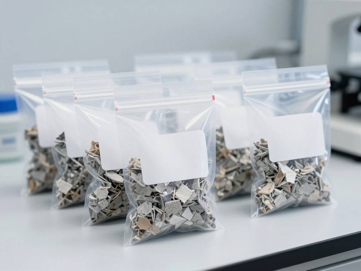
              Samples of PVC and soft plastic cables in sample bags on the test bench
              PVC materials, soft plastics, glues and printing inks are a group that cannot be tested by XRF — chemical testing for phthalates is required.

              6. What is needed in a readable XRF report?

              • Device name and model; measurement mode (e.g. plastic mode, metal mode); measurement time per point.
              • Limit of detection (LOD) and limit of quantification (LOQ) for each element, according to each sample matrix.
              • Decision limits are used for each element (to know the pass/fail/fail zone).
              • Sample description: which sample, what material was removed, shape and thickness.
              • The number of measurement points and the value of each point, not just the maximum value.
              • Conclusion has scope: “screening results”, not “conclusion of conformity”.
              Desktop XRF machine with spectrum display and small samples arranged side by side on the laboratory table
              XRF readings must be accompanied by decision limits, LOD/LOQ, and sample description — single numbers are not conclusive.

              7. Frequently asked questions

              If the XRF passes, is it necessary to test for phthalates?

              Yes, if the product contains materials that pose a risk of containing phthalates (PVC, soft plastics, glues, inks, cables). XRF does not technically test for phthalates, so a “pass” result from XRF does not cover these four substances.

              If the product previously met RoHS 6 substances, will it now automatically meet 10 substances?

              No. Four phthalates were added according to the 2019–2021 roadmap (and 2024 for in vitro diagnostics). The old dossier under 6 substances does not cover the four new substances.

              Can XRF be used at the factory to check 100% of shipments?

              Used for internal control, it is reasonable and very effective. But compliance documentation still requires results according to the standard-specified method, on a representative sample — and must include substances that cannot be measured by XRF.

              Why do two devices give two different results for the same sample?

              Due to differences in calibration, measurement geometry, beam size, measurement time and sample matrix treatment. Deviations between devices are normal; Therefore, results close to the limit should always be treated as inconclusive regions.

              Is the XRF report legally valid?

              The XRF report is part of the assessment record, valuable in accompanying risk assessment and validation results. It does not replace a conclusion of conformity, and it cannot replace chemical results for substances that cannot be measured by XRF.

              8. Conclusion

              XRF is a good screening tool, but Not a conclusive tool. Three things to remember: one, XRF only shows the element so it cannot conclude Cr(VI), PBB/PBDE and cannot test four phthalates at all; two, the result close to the limit is the inconclusive zone, not the pass zone; three, only measurements on homogeneous materials are meaningful.

              References

              • IEC 62321-3-1 — X-ray fluorescence screening
              • Directive 2011/65/EU and Directive (EU) 2015/863 — list of restricted substances and limits
              • European Commission Guidance on the RoHS Directive

              Related articles


              Discuss further


                Disclaimer

                This article is an interpretive content compiled by us; not legal advice and does not replace the technical opinion of an accredited testing laboratory.

                Decision limits, detection limits and specific results handling are specified in the standards and calibration documents of each device; Enterprises need to compare with testing laboratories.

                See more: Copyright Policy & Disclaimer by ticforall.com.

                Batteries and RoHS: why is the EU battery regulation the main application framework?

                0
                Cover image of the article «Batteries and RoHS: why is the EU battery regulation the main application framework?»

                Batteries are one of the most confusing cases when making regulatory compliance documents: the same battery is both in an electrical and electronic device and is also subject to a separate set of regulations with a much stricter limit.

                The practical consequence: a battery can meet the RoHS limit but still not meet the requirements of the battery regulation — and conversely, some battery requirements do not appear in the RoHS filings at all.

                1. Why do batteries have their own set of regulations?

                Batteries have a unique chemical structure, contain heavy metals in compound form and pose a high-risk when disposed of. Europe has developed a separate regulatory framework for batteries, replacing the old battery directive and covering the entire life cycle: from substance limits, labels, information, recycled content to collection and recycling responsibilities.

                Therefore, in the profile of a device with a battery, businesses need to separate two parts:

                • Electrical and electronic equipment part: RoHS compliant.
                • Battery part: Batteries are subject to separate regulations, with separate labeling, information and recycling obligations.

                2. Quality limit: the biggest difference

                Quality RoHS Battery regulations Points to note
                Mercury Threshold according to homogeneous material Very tight limit based on battery weight Batteries and devices have completely different calculations
                Cadmium Thresholds are stricter than other substances, based on homogeneous materials The limit is even tighter based on battery weight This is the substance that most easily exceeds the limit in reality
                Lead Standard limit according to homogeneous material There is a separate limit based on battery mass, applied according to a specified time period It is necessary to check the mark applicable to the specific battery type
                The remaining 10 substances are on the RoHS list Restricted Not within the substance limits of battery regulations RoHS control is still required if part of the equipment

                Bottom line: Different limit calculation methods. RoHS calculated according to homogeneous materials; Battery regulations are based on battery weight. Therefore, businesses cannot infer the results of one set from the results of the other set.

                Batteries and electronic devices are regulated under two different regulatory frameworks
                Batteries and devices are subject to two regulatory frameworks with different limit calculations.

                3. Other requirements of battery regulations

                Request group Content Impact on equipment businesses
                Labels and symbols Separate collection symbols, capacity information and ingredients according to regulations Must be printed on the battery or on the packaging according to specific requirements
                Digital information Product information is associated with code or lookup means Need battery data and device data in structured form
                Declare carbon footprint Applicable to some types of batteries according to the roadmap Businesses purchasing batteries need to ask suppliers to provide data
                Recycled content Require the percentage of recycled materials in batteries according to the roadmap Influences the choice of battery supplier
                Ability to remove and replace Design requirements allow battery replacement in some device groups Directly affects design and assembly
                Expanded responsibility Registration, reporting, responsibility for battery recovery and recycling Administrative obligations parallel those of the device

                4. Five things equipment businesses need to do

                1. Separate battery profile and device profile: two sets of documents, two sets of limits, two sets of documents.
                2. Ask the battery supplier to provide its own data: concentration according to battery volume, not just according to material.
                3. Check applicable milestones according to battery type: New requirements have different roadmaps across battery groups.
                4. Review the design for the ability to replace the battery If the product belongs to the group that must be guaranteed to be replaceable.
                5. Correct labeling of both parts: device label and battery label and symbol.
                Separate collection labels and symbols on batteries and electronic devices
                Battery labels and markings are a separate obligation and are not covered by RoHS requirements.

                5. Five points that are often overlooked

                Point missed Consequences How to handle
                Use the battery material report to make conclusions for the device Missing data for housing, circuit, cable Completely disassemble the device’s materials
                Use the device report to make conclusions about the battery Incorrectly calculating limit based on battery volume Requires separate data according to battery mass
                Forget battery label obligations Goods were held due to lack of prescribed markings Include label inspection in the shipping inspection list
                The need to replace the battery is not taken into account in the new design The design must be corrected after it has been produced Review requirements right at the design stage
                Not following the application roadmap Passive when new landmark takes effect Include the roadmap in the annual conformity review schedule
                The roadmap required by battery regulations is included in the regulatory compliance review schedule
                The battery adoption roadmap should be followed at the same time as the RoHS filing review schedule.

                6. Frequently asked questions

                Are batteries RoHS scoped?

                Batteries have their own set of regulations regarding substance limits. The electrical and electronic equipment containing the battery must still meet RoHS for the details of the device. Businesses should confirm the application for each specific battery type with the testing laboratory and compare current documents.

                Does meeting RoHS mean meeting battery requirements?

                No. The limit for battery regulations is calculated based on battery mass and is stricter for some substances, especially cadmium. Need separate dataset.

                Do replacement batteries sold separately require separate documentation?

                There may be, depending on the battery type and market. This is a group that is often overlooked because it does not come with equipment.

                Do I need to try both sets?

                Usually data is needed for both frames, but it is possible to take advantage: the same material sample can be analyzed according to RoHS requirements, while calculating the results according to battery mass if mass and composition data are available.

                Does the battery replaceability requirement apply to all devices?

                No. This requirement applies by device group and by roadmap. Businesses need to check which product group their product belongs to.

                7. Conclusion

                Batteries and battery-containing devices are subject to two parallel regulatory frameworks with different limit calculations: RoHS according to homogeneous materials, battery regulations according to battery mass. Therefore, the data of one frame cannot replace the other.

                Three things to do: separate battery records from device records; request battery mass concentration data from the supplier; and put label requirements, battery replacement, and application roadmaps on the same review schedule as the RoHS dossier.

                References

                • Regulation (EU) 2023/1542 on batteries and waste batteries, replacing Directive 2006/66/EC.
                • Directive 2011/65/EU and its amendments (RoHS).
                • Directive 2012/19/EU (WEEE) on responsibility for recall of electrical and electronic equipment.

                Related articles


                Discuss further


                  Disclaimer

                  This article is an interpretive content compiled by us; not legal advice. Enterprises need to compare relevant documents/standards verbatim before applying them to specific products.

                  See more: Copyright Policy & Disclaimer by ticforall.com.
                  RoHS and WEEE: one side restricts the substance, the other side is responsible for recall

                  0
                  Cover image of the article «RoHS and WEEE: one side restricts the substance, the other side is responsible for recall»

                  RoHS and WEEE are often mentioned together because they come from the EU’s policy on electrical and electronic equipment, share the same concept of “manufacturer” and aim to reduce environmental impact. But the two sets of regulations address two completely different issues: one side limits substances in products, the other side manages products at the end of their life cycle.

                  Understanding the difference helps businesses avoid two costly mistakes: thinking that achieving RoHS means fulfilling their environmental obligations, or thinking that recall obligations can be treated the same as substance restriction obligations.

                  1. Two sets of rules, two problems

                  Criteria RoHS WEEE
                  Central question Does the product contain a restricted substance that exceeds the limit? How are waste products collected and treated?
                  Time of application Before bringing the product to market After the product reaches the end of its useful life
                  Typical obligations Conformity assessment, CE marking, declaration of conformity, technical documents Register the manufacturer, report the amount put on the market, organize or sponsor recycling collection
                  Subject responsible Manufacturer and importer Manufacturers, importers, distributors, depending on specific obligations
                  Commonly used evidence Test report, material declaration, technical records Registration papers, contracts with data collection and reporting organizations
                  Scope of implementation According to each product, check the sample According to each member state, often associated with environmental agencies

                  Misunderstanding point: WEEE does not require test reports for each product. WEEE’s obligations are administrative and financial, linked to the amount of goods placed on the market and the collection infrastructure of each country.

                  2. WEEE obligations that export businesses often overlook

                  1. Register in each member state. This is a country-specific obligation, there is no general registration for the entire EU.
                  2. Report on volume brought to market by equipment type and by reporting period.
                  3. Financial responsibility for collection and disposal. Usually done through an authorized collection organization or corresponding agreement.
                  4. Labeling according to regulations: crossed-out trash symbol and manufacturer identification information to facilitate retrieval when the device becomes waste.
                  5. Provide information to processing facilities about details and materials that need to be dismantled and handled separately.
                  Thiết bị điện tử đã qua sử dụng được phân loại tại khu thu gom
                  RoHS controls substances in products; WEEE controls the flow of materials after products become waste.

                  3. Intersection point between two sets of regulations

                  Activities Serving RoHS Serving WEEE
                  Easy to dismantle design, easy to separate materials Helps identify homogeneous materials and supports sample removal Helps increase recovery rates and reduce processing costs
                  Restricted substance removal Meets the limit Reduce the amount of hazardous substances entering the waste stream
                  Material records by product code Proof of compliance Provide information to processing facilities
                  Product label CE mark with corresponding documents Unique symbol for waste equipment and identification information
                  Documents with suppliers Material declaration Requires materials and structures for dismantling
                  Thiết bị điện tử có ký hiệu phân loại rác thải điện tử trên nhãn
                  Labels and design information serve both sets of duties, but with different purposes.

                  4. Four common misunderstandings

                  Misunderstanding Reality Consequences
                  “Achieving RoHS is fulfilling environmental obligations” WEEE is a separate set of obligations, usually attached to each member state Sales are not allowed, or fees are collected in the importing country
                  “WEEE only applies to manufacturers in the EU” Non-EU businesses are still obliged to bring goods into the market, usually through authorized representatives Not properly registered, goods are detained at customs
                  “WEEE needs test report” WEEE is primarily a registration, data reporting and financial obligation Preparing the wrong type of documents
                  “One registration can be used for the whole EU” Register by member state Missing a small market but still under control

                  5. General management in a product profile

                  1. Separate two monitoring books: one book for RoHS technical records by product code, one book for WEEE obligations by exporting country.
                  2. Attach a time stamp: product-to-market dates for both, as WEEE also has periodic reporting milestones.
                  3. Identify authorized representative: If the business is outside the EU, a representative is required to be responsible for fulfilling obligations in each country.
                  4. Shared material data: Material removal records serve both RoHS assessment and information for the disposal facility under WEEE.
                  5. Periodic review: list of restricted substances that can be supplemented; WEEE regulations by country also change over time.
                  Trao đổi hai bộ hồ sơ hợp quy và trách nhiệm tái chế trong doanh nghiệp
                  The two groups of obligations should be managed in parallel but with two different sets of criteria.

                  6. Frequently asked questions

                  Does WEEE apply to components sold separately?

                  Normally WEEE applies to complete equipment, not to separate components. However, it is necessary to check the device definition of each member state and each specific case.

                  Do businesses in Vietnam have direct WEEE obligations?

                  Non-EU businesses cannot register directly in many countries; Obligations are usually performed through the importer or authorized representative according to each country’s requirements. The contract should clearly state which party is responsible and the costs.

                  Is it mandatory to have a crossed-out trash can symbol?

                  This is a common labeling requirement under WEEE, used to distinguish equipment that should not be disposed of with household waste. Detailed content and exceptions should be compared with the current regulations of each country.

                  Does RoHS filing help with WEEE obligations?

                  Yes, the material take-off and detailed list are shared for providing information to processing facilities. But WEEE still needs its own set of documents for registration and reporting.

                  How are WEEE costs calculated?

                  Depending on the mechanism of each country: some places are attached to authorized collection organizations, some places require financial guarantees. Businesses should ask the importer or authorized representative about the fees applicable to each product group.

                  7. Conclusion

                  RoHS and WEEE are two sets of parallel obligations, not replacing each other: RoHS talks about substances in products, WEEE talks about products when they become waste. Both are associated with the concept of manufacturer but at two different points in the product life cycle.

                  Three things to do: separate two duty tracking books for each product code and each country; clearly identify the authorized representative responsible for WEEE; and share material removal data for both sets of records to save effort.

                  References

                  • Directive 2011/65/EU and its amendments (RoHS).
                  • Directive 2012/19/EU on waste electrical and electronic equipment (WEEE) and the conversion regulations of individual member states.
                  • European Commission guidance on the phased application of WEEE.

                  Related articles


                  Discuss further


                    Disclaimer

                    This article is an interpretive content compiled by us; not legal advice. Enterprises need to compare relevant documents/standards verbatim before applying them to specific products.

                    See more: Copyright Policy & Disclaimer by ticforall.com.
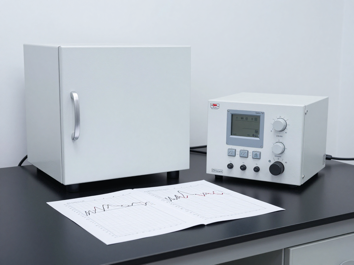
                    RoHS and plastic recycling: why is it most difficult for recycled plastic to achieve RoHS?

                    0
                    Cover image of the article «RoHS and plastic recycling: why is it most difficult for recycled plastic to achieve RoHS?»

                    Of all the material groups, recycled plastics are the most difficult to achieve RoHS. Not because recycled plastic is inherently bad, but because it carries with it the history of previous products — including additives that are now restricted.

                    This article explains four groups of substances that often “migrate” with recycled plastic, why testing recycled plastic is more difficult than virgin plastic, and six steps to building a practical control program.

                    1. Why is recycled plastic the highest risk point?

                    Characteristics Primary plastic Recycled plastic
                    Origin Determined, as declared by the manufacturer Often not fully identified, across multiple layers of collection
                    Additive ingredients According to registered formula May contain additives from older products
                    Uniformity between batches High Low, varies with input source
                    Document traces There is a material declaration Often lacking or only at a general level of commitment
                    Risk exceeds the limit Low High

                    The bottom line: recycled plastics were a product of another time, when substances like organic brominated flame retardants or certain plasticizers were commonly used. When that plastic turns back into raw materials, the old substances come back with it.

                    2. Four groups of “sequelae” in recycled plastic

                    Substance group Common origin Risk level
                    Organic brominated flame retardants (PBB, PBDE) Old electronic device covers, plastic from machinery and household electrical appliances Very high — this is the most common reason why recycled plastics fail
                    Plasticizing the phthalate group PVC from old cables, pipes, and plastic films High — especially with soft plastics
                    Cadmium and lead in colorants and stabilizers Yellow, orange, red plastic; Old PVC High — cadmium has a tighter limit
                    Other halogenated flame retardants Plastic from old equipment and construction materials Medium with RoHS, high with customer halogen-free requirements

                    Note to the last group: many brominated flame retardants are not on the RoHS restricted list, but are still excluded in halogen-free claims or in customer purchasing policies. Therefore, recycled plastic often entangles both layers of requirements at the same time.

                    Hạt recycled plastic các màu được kiểm tra trên bàn phòng thử
                    Recycled plastic carries additives from previous products, including restricted substances.

                    3. Why is it more difficult to test recycled plastic than virgin plastic?

                    1. Inconsistent: Composition varies between grains, between bags and between batches. A small sample may not be representative of the whole lot.
                    2. Physical dispersion: Flame retardants may concentrate in some pieces of plastic while the rest is clean.
                    3. Influence of sample background: resins with fillers, reinforcing fibers, or dark colors make screening results less stable.
                    4. Missing source data: Without knowing which product line the plastic comes from, it is impossible to assess risks by substance group.

                    Practical consequence: with recycled plastics, sampling and sample quantity are as important as the analytical method. Taking a small sample from one bag cannot be concluded for the whole lot.

                    Chuẩn bị nhiều mẫu recycled plastic từ các bao khác nhau để kiểm tra
                    With recycled plastics, representative sampling is as important as the analytical method.

                    4. Six steps to control recycled plastic

                    # Step Specific requirements
                    1 Choose controlled sources of recycled plastic Prioritize sources from defined product lines instead of mixed common plastics
                    2 Request batch records Origin, product line, import date, batch code
                    3 Screen each batch of raw materials The screening index is lower than the limit to create a safe zone
                    4 Test periodically according to analytical methods Organic bromine group, plasticizer group, heavy metal
                    5 Separating material streams at the factory Do not mix certified recycled plastic with uncertified plastic
                    6 Recorded in the supply contract Provisions for notification of source changes and liability when limits are exceeded

                    5. There are no exemptions for recycled plastics

                    Here’s the point: RoHS has no exemptions for recycled materials. Products made from recycled plastic must still meet the same limit as products made from virgin plastic. Using recycled materials is an environmental choice, not a basis for lifting the limit.

                    At the same time, the pressure to increase recycled content in products is increasing. Enterprises therefore have to solve two problems at the same time: increasing the rate of recycled materials and maintaining evidence of conformity for that material.

                    Khu vực lưu trữ nhựa nguyên sinh và recycled plastic được tách riêng
                    Separation of confirmed and unconfirmed material flows is a mandatory control measure in the plant.

                    6. Frequently asked questions

                    Can recycled plastic from old electronic device casings be used?

                    Possibly, but this is the highest risk group because of the greatest likelihood of containing organic brominated flame retardants. It is necessary to control each batch and test according to appropriate analytical methods.

                    Is there a way to quickly screen bromine flame retardants at the factory?

                    A screening device that measures total bromine can be used, but the results are only indicative. Conclusions must be based on analytical methods to identify compounds.

                    If recycled plastic only makes up a small percentage of the product, does it have to be inspected?

                    Yes. The limit applies to each material uniformly, regardless of the ratio in the product.

                    Can a recycled plastic supplier issue a “RoHS compliant” certificate?

                    It is possible, but a test report with batch data and resin source description should be requested. A general confirmation does not indicate whether a particular lot passes or fails.

                    Should recycled plastic be avoided completely?

                    Not necessarily. With recycled plastic from a defined and controlled product stream in batches, the risk can be managed. What should be avoided is using mixed recycled plastics of unknown sources without a control program.

                    7. Conclusion

                    Recycled plastic is the most difficult to achieve RoHS because it carries additives from previous life cycles, composition is inconsistent, and a documentation trail is often lacking. There are no exemptions for recycled materials in RoHS.

                    Three things to do: choose recycled plastic sources from a defined product line; control each batch of raw materials instead of checking once; and separate the flow of confirmed material from unconfirmed material within the plant.

                    References

                    • Directive 2011/65/EU and its amendments (RoHS) — limits apply according to homogeneous materials, with no exemption for recycled materials.
                    • IEC 62321-3-2 — screening of total fluorine, chlorine, and bromine in electrical and electronic products.
                    • IEC 62321-8 — determination of phthalate groups in polymer materials.
                    • Recycled content requirements in the EU sustainable product ecodesign regulation.

                    Related articles


                    Discuss further


                      Disclaimer

                      This article is an interpretive content compiled by us; not legal advice. Enterprises need to compare relevant documents/standards verbatim before applying them to specific products.

                      See more: Copyright Policy & Disclaimer by ticforall.com.