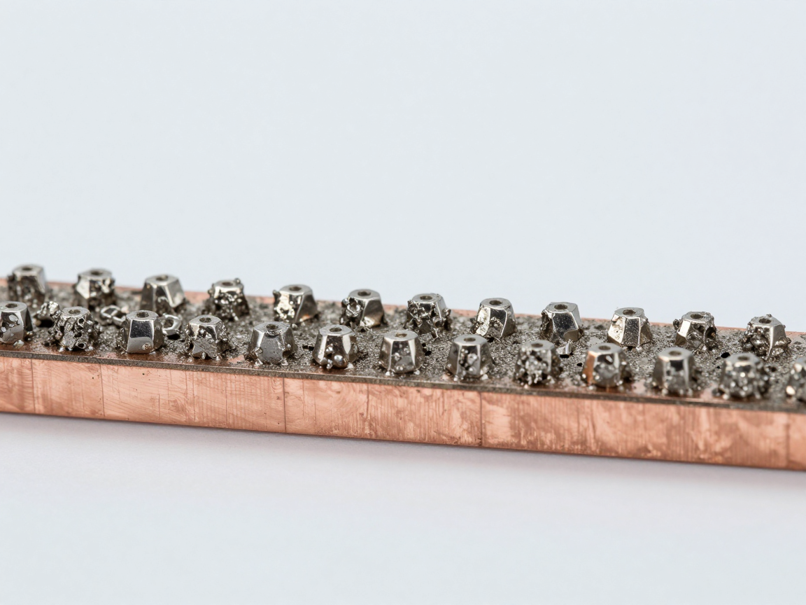
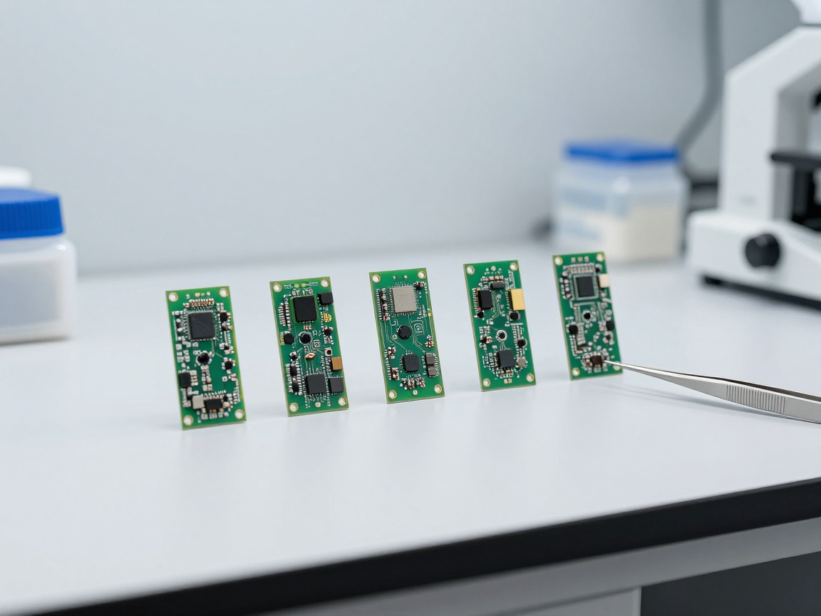
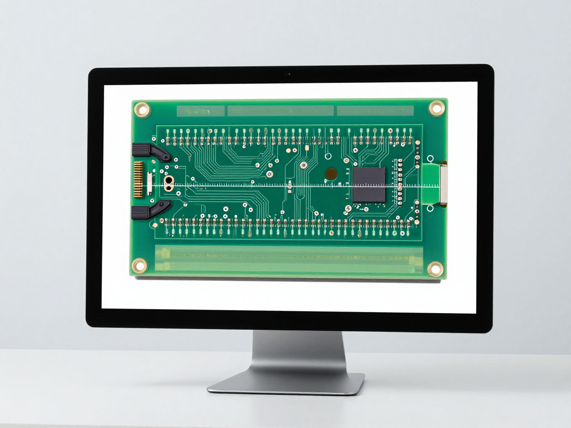
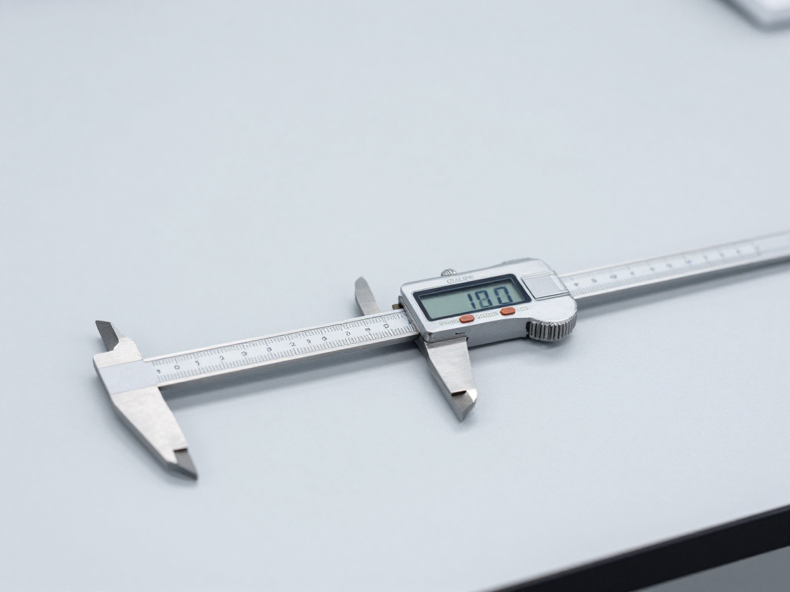
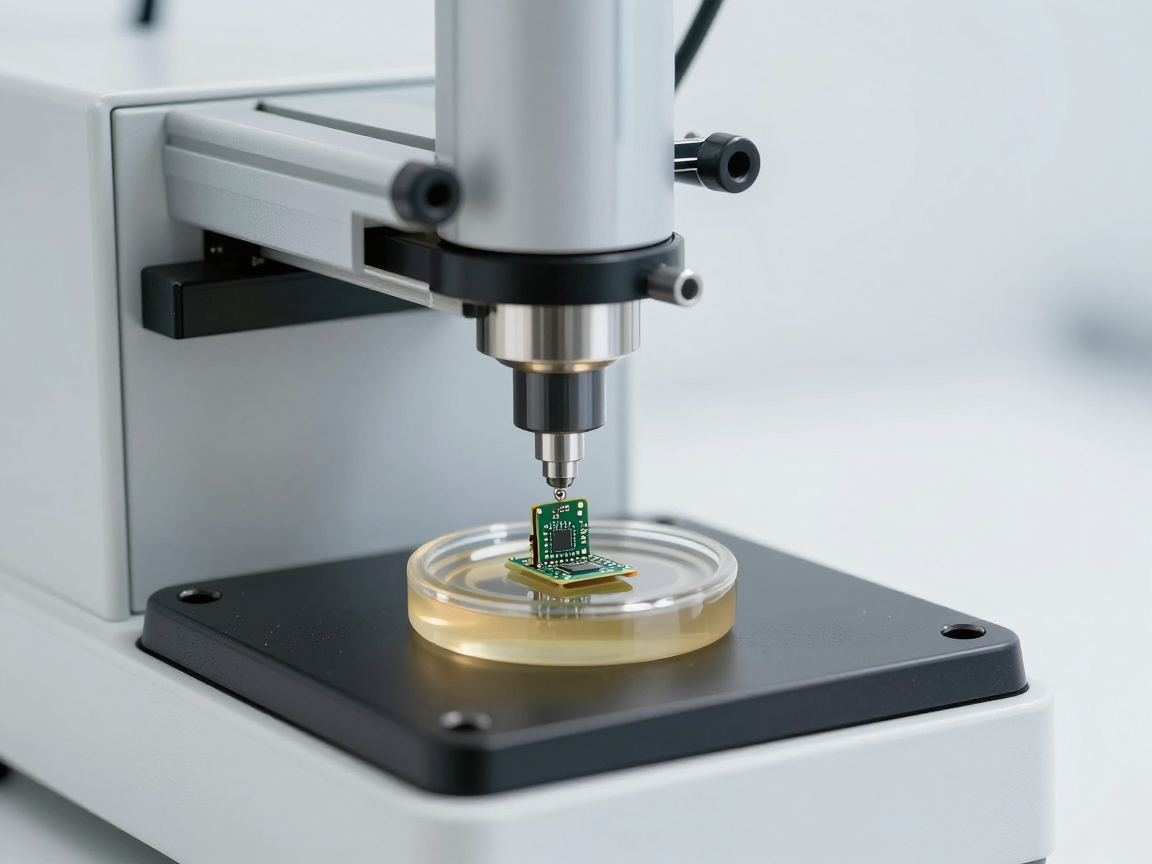
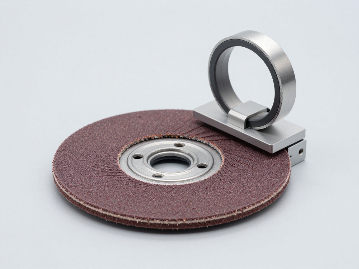
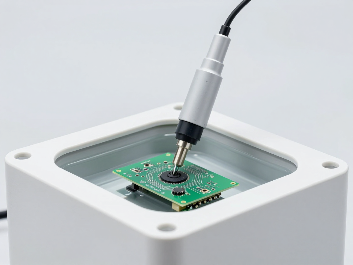
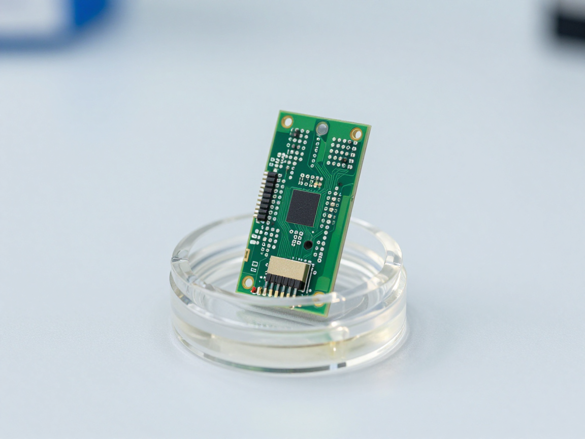
The solder joint is a connection point that is both conductive and resistant, and almost all of its true quality lies in the invisible part: below the component base, inside the tin block, at the interface with the pad. Cross-sections are the only way to read those.
This article explains three characteristics to read on a solder joint cross-section — wetting angle, fillet penetration, and intermetallic compound (IMC) layer — and four common errors and limitations when drawing conclusions from cross-section images.
1. Why must solder joint joints be evaluated by cross-section?
Three main reasons:
The most important part is not visible: The bond between tin and the metal surface is hidden under the component base.
Appearance can be misleading: A solder joint that looks good from the outside may still be hollow on the inside or not completely wet.
It is necessary to distinguish process errors from design errors: only the internal structure tells which one is the cause.
2. Three characteristics to read on the cross-section
Characteristics
Meaning
Normal signs
Signs to pay attention to
Wetting angle
Indicates whether tin “eats” into the metal surface or not
Smooth concave surface, continuous transition from pad to component pin
Indicates the amount of tin adhered to the component pins
The tin rises evenly along the foot, with a stable thickness
Too little tin adheres or flows into a block on one side
Intermetallic layer
Is evidence of real metallic bonding
Thin strip evenly along the interface
No band is seen, or the band is too thick, or the band is not continuous
These three characteristics complement each other. Missing one of the three, the conclusion about the solder joint is still not well-founded.
A smooth, concave wetting angle is a sign that the tin has flowed properly and bonded to the surface.
3. Wetting angle: how to read?
The wetting angle is the angle formed by the tin surface with the base metal surface at the interface. How to read on the cross-section:
Small angle, concave surface: Tin spreads evenly and bonds well.
Large angle, convex surface: Tin shrinks into a sphere, with poor bonding ability.
Clear broken boundary: signs of surface contamination or oxidized coating.
One point that is easily overlooked: for the same solder joint, the wetting angle on the pad side and the component leg side may be different. When reading, you should clearly state which side you are evaluating.
4. Foot absorption: landmark determines the result
How to calculate
How to do it
Risk
Calculated from the pad surface
Measure the tin height from the pad surface up to the feet
Ignore the tin located at the foot
Calculated according to solder joint thickness
Compare the tin adhesion height to the total pin thickness in the solder joint
It is necessary to clearly identify the foot landmark
Calculated according to component thickness
Compared to the thickness of the component body
Not suitable for components with long legs
Because there are many calculation methods, the report must clearly state the method used. In quality disputes, most disagreements about “enough tin or not enough tin” are actually disagreements about quality.
5. Intermetallic layer: evidence of metallic bonding
When molten tin comes into contact with copper, an intermetallic alloy layer is formed at the interface. This is evidence that the bond has formed at the metal level, not just surface adhesion.
Condition of the intermetallic compound (IMC) layer
Implication
Risk
Very thin or invisible
Maybe the heat is not enough or the surface is not clean
Weak bond, easy to separate when subjected to force
Thin and continuous
Desired state
No worries
Abnormally thick
The temperature or holding time is too high, or the solder joint has been worked at high temperature for a long time
Brittle, easy to crack when subjected to vibration or thermal shock
Discontinuous, interrupted
Unlinked region
Crack initiation point
Note: the intermetallic compound (IMC) layer continues to thicken over time at high temperatures, even after the product has passed the output test. Therefore, evaluating the intermetallic compound (IMC) layer needs to be placed in the context of the actual working conditions of the product.
If the intermetallic compound (IMC) layer is too thin, the bond is weak, if it is too thick, it becomes brittle.
6. Four common errors on the solder joint cross-section
Error
Marks on the cross-section
Common causes
Local tin deficiency
The tin block is thin, does not cover all the components
The amount of solder paste is not enough, the pad design is skewed
Crack at the heel of the solder joint
The crack originates from the outer edge of the solder joint
Mechanical stress when bending the circuit board, difference in thermal expansion
Void concentration
Large voids in the load bearing area or heat conduction area
The air cannot escape in time, the solder paste is damp, and the heat profile is not optimal
Not wet
Broken boundary between tin and surface, with gaps
Always have a control sample to distinguish real abnormalities from normal solder joint characteristics.
7. Limitations when drawing conclusions from cross-sectional images
Only see one plane: voids or cracks outside the section will not appear in the image.
Small sample, limited quantity: A successful solder joint does not prove that the entire circuit board is successful.
Influence of sample preparation: Too much grinding can erase the intermetallic compound (IMC) layer or create fake marks.
Does not reflect the entire sample history: A solder joint that has been heated many times has a different structure than a solder joint that has been heated only once.
8. Minimum information in the report
Position of cut solder joint and cutting direction.
The photo is magnified enough to see both the component pins and the pad, with a scale.
Separate magnified image for the area of interest (wetting angle, intermetallic compound (IMC) layer, void).
Conclusion for each feature, separate from the description.
Standards and product classes apply for evaluation.
9. Frequently asked questions
Does a solder joint that looks good on the outside need to be cut and inspected?
With first batches, new products or when there are questions about the procedure, inspection should be done. External appearance does not prove internal connection.
Is there a way to measure the intermetallic compound (IMC) layer without destroying the sample?
There is no non-destructive method that gives equivalent results at the microscopic scale. Ultrasound and X-ray can suggest but cannot measure the thickness of the intermetallic compound (IMC) layer.
What percentage of Void is considered an error?
The threshold depends on the applicable standard, component type and product class. In addition to ratio, it is necessary to consider the size of each void and their position in the solder joint.
Which magnification should I choose for shooting?
Take two levels: one wide enough to see the entire solder joint and its relationship to the pad, one high enough to see the intermetallic compound (IMC) layer boundary.
What if both the pad and foot are good but there are still errors?
At that time, factors other than the solder joint should be checked: stress from the circuit board, assembly force, or thermal conditions during use.
10. Conclusion
The solder joint cross-section answers three questions: is the tin wetted properly, is there enough tin on the pin, and is a metallic bond formed. These three answers combined allow a conclusion about the solder joint.
Four things to do: clearly state the infiltration benchmark in the report; Shoot at two magnification levels; always have a control sample; and clearly state the limitation of conclusions due to the method observing only one cutting plane.
References
IPC-A-610 — Electronic assembly acceptance criteria, solder joints with pins.
J-STD-001 — Requirements for electrical soldering and electronic assembly.
This article is an interpretive content compiled by us; not legal advice. Enterprises need to compare relevant documents/standards verbatim before applying them to specific products.
A common phenomenon in cross-section evaluation: two testing laboratories receive the same sample, measure the same criteria, but produce two different numbers. The cause often lies not in the equipment, but in the calibration method and the definition of the measuring point.
This article guides the correct procedure for measuring on cross-sectional images: calibrating the scale, defining measurement points for each criterion, handling errors, and how to record results for reproducibility.
1. Why does the same sample give three different numbers?
Cause
How to express
Influence
The scale has not been calibrated properly
Deviation is proportional between measurements
Systematic error across all results
Use different magnifications but apply the same factor
The numbers vary by degree
Serious errors, easy to detect if compared
Different measurement point definitions
Small, uneven deviation
Difficult to detect, causing long debate
The cutting surface is beveled or not flat
Measured thickness is larger than actual
Error depends on measurement location
The measurer chooses the bias measurement point
Results tend to follow expectations
Measurement points should be specified in drawings
The uncalibrated scale makes all the numbers behind lose their value, even though the image is very sharp.
2. Calibrate the scale before every measurement
Use a standard slide with known graduations to establish the relationship between the actual distance and the number of pixels or divisions.
Perform separate calibration for each objective and for each magnification level to be used.
Check again during the shift or before each important sample set, not just on a long periodic schedule.
Record the calibration results with device code, date, and person performing it.
One point that is easy to miss: when the imaging system changes (changing cameras, changing glass body height, changing image processing software), it must be recalibrated even if the device is not yet in maintenance period.
3. Define measurement points for each indicator
Target
Definition of measuring point
Note against errors
Plating thickness in hole
Measure at many locations on the hole wall: near the hole mouth, middle of the wall and near the bottom
Specify whether to take the minimum value or the average value
Surface coating thickness
Measure perpendicular to the surface, in a flat area, avoiding transition areas
Avoid measuring at beveled edges where the coating is unusually thin
Contact ring around hole
Measure the smallest distance from the hole wall to the edge of the pad
Measure at the smallest position, not at the widest position
Tin absorption on component pins
Measure the height of the tin on the pin compared to the total thickness of the solder joint
Clearly determine the landmark from the component foot or from the pad
Thickness of intermetallic compound (IMC) layer
Measure in the middle of the interface, measure multiple times and average
Avoid measuring in areas with corners or impurities
void size
Measure the largest diameter and estimate the area
Specify how to determine the void boundary
The most effective way: accompany the report with a drawing or photo with the location and direction of measurement marked. When both sides look at the same image, arguing about numbers will be much shorter.
Each criterion needs a unified measurement point definition, otherwise the results between testing laboratories will vary.
4. Error handling: three sources need to be separated
Source of error
Characteristics
How to handle
Systematic error
Deflect evenly, in the same direction at every measurement
Recalibrate; Compare with standard sample
Random error
Fluctuates around the average value
Measure multiple times, average and record dispersion
Error due to sample preparation
Deviation according to position on the section
Measure in a flat area, check the sample again before measuring
Practical rule: each number included in the report should have context — number of measurements, minimum and maximum values, magnification. A single number without context is difficult to defend when questioned.
5. Record the results for reproducibility
Measurements, units (micrometers or mils) and conversions if necessary.
Magnification and equipment used.
Measurement location on the sample, described by picture or location code.
Standards and product classes apply for evaluation.
Original photo with scale displayed in the frame.
Date of measurement, person measuring and person checking again.
6. Five errors cause measurements to be unreproducible
Scale not shown in photo.
Measured on images that have been processed to increase contrast but do not save the original image.
Mix units of measure between items in the same report.
The magnification is not recorded so it cannot be checked again.
Measured on a chamfered sample without recording the sample condition.
Measurement standards and measuring equipment must be part of a periodic calibration program.
7. Frequently asked questions
Should results be reported in micrometers or mils?
Depends on customer conventions and applicable standards. The safest way is to clearly state the unit and include the conversion, to avoid confusion between parties.
Should it be measured automatically by software?
Automated measurements help reduce subjective errors and increase speed, but people still need to double-check boundary cases — where class boundaries are unclear.
What if the area to be measured is only a few micrometers wide?
It is necessary to increase the magnification, recalibrate the scale at that magnification level, and measure many times at many locations to have a statistical basis.
How many points should a sample measure?
There is no fixed number. The principle is enough to see the distribution — if the measurement points differ greatly, it is necessary to increase the number of points instead of averaging immediately.
What is the allowable error of measurement?
Depends on equipment, magnification and applicable standards. Should be clearly defined and recorded in internal procedures, and periodically checked using standard samples.
8. Conclusion
Variations between testing laboratories are rarely due to equipment, but are usually due to three factors: improperly calibrated scale, different measurement point definitions, and beveled or uneven samples. All three can be prevented by process.
Four things to do: calibrate the scale for each magnification before each set of samples; Specify measurement points with drawings instead of words; Record the number of measurements and dispersion next to the average value; and always save the original image with the scale.
References
IPC-TM-650 Method 2.1.1 — Microsectioning, section measurement and evaluation.
IPC-A-600 and IPC-6012 — Criteria and technical requirements related to plating thickness and contact rings.
IPC-7095 — Void Evaluation for BGA.
Requirements for calibration and control of measuring equipment in the testing room quality management system.
This article is an interpretive content compiled by us; not legal advice. Enterprises need to compare relevant documents/standards verbatim before applying them to specific products.
In the cross-section, the microscope is just the one recording the results. What determines whether the image shows structure or not lies in the four previous steps: cutting, molding, grinding and polishing. An incorrectly prepared sample can hide real defects, or create false defects that do not exist.
This article describes each step, the typical errors of each step, how to recognize a damaged sample and how to reduce it depending on the skill of the operator.
1. Sample preparation chain and principles throughout
Cut — separate the area to be surveyed from the details.
Casting — secure the pattern in the plastic mold and protect the cut edge.
Grinding — bring the section to the correct plane to be examined.
Polishing — removes scratches and surface deformation layers.
Corrosion — increase structural contrast, use only when needed.
Cross-cutting principles: Each step must be processed enough to eliminate the influence of the previous step, but not processed so much that the part to be examined is lost.. Most sample preparation errors are violations of one of the two sides of this principle.
2. Sample cutting: control heat and cutting plane
Factor
Need control
If you do it wrong
Cutting blade
Choose the type of abrasive suitable for the material
Grinding too hot, burning edges, deforming the plating layer
Cooling solution
Enough flow, right spray direction
The heat generated softens the base plastic and deforms the solder joint
Cutting speed
Slow for samples with small solder joints, faster for thick metal samples
The cut is beveled, small details are lost
Clamp direction
Perpendicular to the axis you want to survey
Measured thickness is larger than actual
Signs of sample damage due to cutting: burned cutting edges, scratched metal layer along the blade direction, plastic plastic deformation. When seeing these signs, conclusions about thickness should be kept cautious.
Casting helps hold the pattern in place and protects the cut edge — the edge is the most vulnerable to damage.
3. Molding the pattern: holds it in place and protects the edge
Method
Characteristics
Fits
Hot molding (thermoplastic)
Quickly, the sample is pressed under conditions of heat and pressure
Metal samples, circuit boards, and heat-resistant parts are good
Cold molding (two-component resin)
No heating, longer setting time
Heat-sensitive samples: small solder joints, plastics, soft materials
Three common errors in the molding step: plastic flows into the gaps between the parts, causing wrong edges of the sample; The sample moves during the setting process; and shrinking plastic creates a gap between the sample and the plastic — this gap when ground will attract impurities and create fake streaks in the image.
4. Grinding: downgrading the grain step by step
Phase
Purpose
Signs of needing to move forward
Rough grinding
Flatten and approach the correct plane to be examined
The entire cross-section is flat, no cuts remain
Middle grinding
Type the large scratch from the previous step
Unidirectional scratches
Fine grinding
Kind of small scratches
The surface is evenly matte, no scratches can be seen at low magnification
Two common mistakes: skipping a certain grain level (resulting in deep scratches remaining at the end) and grinding in a single direction for too long (resulting in an uneven surface, with one side beveled).
5. Polishing: processing the deformation layer
Grinding creates scratches, and polishing creates a thin layer of deformation on the surface. This layer can hide small details such as the intermetallic compound (IMC) layer or make the plating layer appear thicker than it actually is.
Phenomenon
Common causes
How to handle
The comet’s trail extends
Polishing too long at one speed causes the hard piece to drag
Reduce time, change direction, clean fabric
Impurities stick to streaks
Fabric is dirty, sample is not washed between steps
Wash and dry the sample between steps
The edge of the sample is rounded
Pressure too high or polishing too long at the edge
Reduce force, use a stand to keep the sample stable
The plating looks unusually thick
The deformation layer is included in the thickness
Polish again with a finer grit
Ignoring grain levels will leave scratches and distortion layers that obscure the true structure.
6. Corrosion: when needed and when not
Corrosion is used to increase contrast between phases in metals or between layers of materials. With circuit boards and solder joints, etching is often used to highlight grain boundaries and intermetallic compound (IMC) layers.
Situation
Should it corrode?
Reason
Measure the thickness of the plating layer
Usually not
The layer boundaries were clear enough by optical contrast
Evaluate solder joint grain structure
Yes
Contrast is needed to read grain size and morphology
Measure the intermetallic compound (IMC) layer
Depends on the situation
Light corrosion helps differentiate, strong corrosion can dissolve the very layer to be measured
Evaluate corrosion defects in products
No
Corrosion products are evidence, no further alterations should be made
Safety principle: prepare two identical samples, corrode one sample and keep one sample intact. If the corrosion sample gives questionable results, there is still a control sample to test.
7. Five signs the sample has passed before measuring
Flat surface, evenly reflective under slanted light.
There are no visible scratches at working magnification.
The boundaries between layers are sharp and not blurred.
There are no gaps between the sample and the molded resin.
The smallest details that need to be surveyed are still intact, without beveled or lost edges.
An uneven cross-section will cause any rear thickness measurements to be incorrect.
8. Frequently asked questions
Can a regular metal cutter be used to cut samples?
Shouldn’t. Conventional cutting machines generate great heat and force, easily deforming small solder joints and plating layers, making measurement results no longer reliable.
Can plastic or soft material samples be used as cross-sections?
Yes, but cold casting and finer abrasives should be used. Soft materials are prone to chamfering, so it is necessary to reduce force and shorten the time each step takes.
Does hand polishing give good enough results?
For screening purposes, it is possible. For the purpose of measuring thickness or analyzing intermetallic compound (IMC) layers, equipment with force and speed control should be used to reduce errors between measurements.
How long does it take for a sample to oxidize and need to be re-prepared?
Depends on material and storage conditions. For copper samples or samples with thin coatings, measurements should be made shortly after polishing and stored in a sealed container with a dehumidifier.
Is there any way to reduce the difference between the two technicians?
Yes: standardize the step-by-step process with fixed parameters, use the same materials, and periodically have two people prepare parallel samples from the same part for comparison.
9. Conclusion
The quality of cross-sectional images is determined in the four steps of sample preparation, not in the microscope. Each step has a characteristic error pattern, and each error pattern leaves a recognizable mark on the image.
Four things to do: control heat and coolant at the cutting step; Choose hot or cold casting according to the sample’s thermal sensitivity; downgrading abrasives in the correct order; and keep an uncorroded sample as a control.
This article is an interpretive content compiled by us; not legal advice. Enterprises need to compare relevant documents/standards verbatim before applying them to specific products.
A cross-section sample set is only valuable when the cutting position correctly answers the question at hand. Cutting in the wrong place, even though the photo is very sharp and the measurements are very accurate, is still inconclusive — and once the model is destroyed, it cannot be remade.
This article provides instructions on how to determine cutting positions according to analytical goals, how to sample in batches, how to mark and orient samples, and the required information that must be included.
1. The question of deciding where to cut
The correct order is always: determine the question first, choose the cutting location later. Doing the opposite — cutting first and then thinking about what to ask — is the most common cause of having to take a second sample.
Questions need answering
Cutting position
Key criteria
Is the plating thickness in the hole satisfactory?
Through the row of marbles at the center and edge positions
Void size and distribution
Is the circuit board misaligned?
Panel edge area and middle panel area
Number of layers, bias, dielectric thickness
Is the drill hole cracked?
The correct hole has increased resistance, along with the control hole
Continuity of the plating layer
Does the crimp terminal compress enough?
Along the body of the crimp terminal, keep the pressure area intact
Compression, void, broken string rays
The cutting position must be related to specific questions: plating thickness, solder joint void or layer misalignment.
2. Four principles for choosing cutting locations
Representative: For questions about batch capacity, sample from multiple locations (edges, middle, high-density areas) instead of multiple samples from the same location.
There is evidence: Always take another passing sample for comparison. Control images help distinguish real abnormalities from normal characteristics of the sample.
Right direction: The cutting plane must be perpendicular to the axis to be surveyed. Cutting diagonally will make any measured thickness larger than it actually is.
Keep backup samples: For important samples, keep an intact portion of the same part so you can cut again if the first attempt fails.
3. Batch sampling: three common ways
How to take samples
How to do it
Advantages
Limitations
Coupons are pre-designed on the panel
Use the coupon area attached to the panel that the designer has reserved
Does not affect the product; Fixed location should be comparable between batches
Not all designs have coupons
Sample from panel edge area
Cut out the non-functional area at the edge of the panel
Take advantage of the waste, save money
It is necessary to check whether the boundary conditions are the same as the middle area or not
Sample from real product
Directly cut the product or assembled circuit board
Correctly reflects production conditions
Loss of product; Need a legitimate reason
Practical recommendations: use coupons for periodic monitoring, use real products when analyzing problems — because then the question is no longer “is the procedure stable” but “what happened to this product”.
Coupon patterns in the same position between batches allow comparison of data over time.
4. Mark and orient the sample
Things to do
How to do it
Why is it important?
Mark the cutting plane
Use colored tape or an oil pen to draw a cutting line on the outside of the template
Avoid misdirection once the sample has left the factory
Record arrow direction
Draw an arrow pointing from which edge, going in which direction
The section must maintain the correct direction for comparison with the drawing
Write down the identification code
Lot code, board code, date, location symbol
Without the code, the data set loses its ability to be retrieved
Do not write on the area to be examined
Only write on the opposite side or outside the survey area
Pen ink and glue can eat into the surface to be analyzed
5. Packaging and transportation
With assembled models, the two main risks are impact and moisture:
Wrap each sample individually in an anti-static bag or sealed plastic bag, with a code slip in the bag.
Fix the sample so that the part to be analyzed does not come into contact with other materials.
If the area to be investigated has a small solder joint, it should be fixed with a stand instead of letting the sample lean against each other.
Add a desiccant package when transporting long distances or during the rainy season.
If the sample is a circuit board that has been tested for corrosion or humidity, this condition must be clearly stated in the submission form: the corrosion results on the cross-section depend greatly on how the sample is preserved after the test.
Clamping in the wrong direction or skewing the cutting plane will cause the sample to lose value and have to be retaken.
6. Mandatory information attached
Specific questions need answering.
Batch code, product code and manufacturing date.
Cut location and desired cutting direction.
Standards and product classes apply for evaluation.
Related design requirements (desired plating thickness, hole diameter, number of layers).
History of the sample: any tests passed, any known abnormalities.
Control sample (if any).
Technical contact information to discuss when clarification is needed.
7. Frequently asked questions
Can I send a whole panel instead of a pre-cut sample?
Yes, and in many cases this is a better way: the test room will choose the cutting position according to the question. The condition must clearly state the request and indicate which parts cannot be cut.
Can a sample that breaks along the cut line still be used?
Usually not, because the broken edge distorts the layer to be measured and creates false defects. It is necessary to keep the sample intact until cutting with specialized equipment with cooling.
How many positions should be cut for a routine check?
There should be a minimum of three different positions representing different risk areas on the panel, rather than three adjacent samples.
Do samples that have passed the thermal shock test need to be sent with samples that have not been tested?
There should be. The “tested – not tested” sample pair is the only way to distinguish pre-existing errors from errors that arise during testing.
Should we take photos of samples before sending?
So, especially with samples that have visible abnormalities. Photos before sending help compare and avoid arguments about sample condition at the time of delivery.
8. Conclusion
Choosing the cut location is the cheapest but most influential step in the entire cross-section process. The question determines the position, the position determines the measurement criteria, and the measurement criteria determines the value of the conclusion.
Four things to do: always have a control sample; Sampling at many different locations when evaluating batch capacity; Mark the cutting direction clearly; and include specific questions and complete retrieval information.
References
IPC-TM-650 Method 2.1.1 — Microsectioning, site selection and sample preparation.
IPC-A-600 and IPC-6012 — Printed circuit board technical requirements and acceptance criteria.
This article is an interpretive content compiled by us; not legal advice. Enterprises need to compare relevant documents/standards verbatim before applying them to specific products.
Cross-sections do not have a single standard. It is located at the intersection of three different groups of documents: the group specifying test methods, the group specifying technical requirements of the board, and the group specifying solder joint acceptance criteria. Misquoting groups is the most common error in cross-sectional reporting.
This article classifies standards according to the subject of assessment, points out which ones regulate what, how to properly cite them in reports, and four common mistakes.
1. Why are there so many standards at the same time?
In an assembled circuit board there are at least three different objects, and each object has its own set of standards:
Bare board: is the responsibility of the board manufacturer.
Welding and assembly process: is the responsibility of the assembly plant.
Test method: specifies how to cut, grind, polish, and measure — not specify an acceptance threshold.
Therefore, a standard sectional report often must reference simultaneously: a standard on test methods, a standard on technical requirements, and a standard on acceptance criteria.
2. Commonly used standard classification table
Standard
Object
Regulate what?
Properties
IPC-TM-650 Method 2.1.1
Test method
Process for preparing cross-sectional samples for printed circuit boards
Technical instructions
IPC-A-600
Bare circuit board
Observable acceptance criteria, including on cross-section
Acceptance criteria
IPC-6012
Hard circuit board
Feature and technical requirements: plating thickness, annular ring, plating continuity
Technical requirements
IPC-6013
Soft circuit board
Technical requirements for soft and soft–hard circuit boards
Technical requirements
IPC-6016
HDI board
Requirements for high density boards with microvia
Technical requirements
J-STD-001
Assembly process
Requires materials and solder jointing process
Process requirements
IPC-A-610
Assembled circuit board
Weld acceptance criteria for each product layer
Acceptance criteria
IPC-7095
BGA
Design, assembly and void evaluation for BGA
Specialized instructions
Points to remember: IPC-TM-650 2.1.1 prescribes how to do this, also IPC-A-600, IPC-6012 and IPC-A-610 define what constitutes. Mixing these two groups is a common reason why reports are questioned.
The standard indicates the acceptance threshold; Conclusions must still be based on actual measurements.
3. Three different types of thresholds need to be distinguished
Threshold type
Who placed it?
Content example
When will it change?
Design threshold
Customer or designer
Desired plating thickness, hole diameter, number of layers
According to each project
Standard threshold
Industry standards
Minimum conditions for the product to be considered satisfactory
According to the standard version
Internal threshold
Factory
Tighter control level than standard to create a safe zone
According to process data
Practical approach: take the standard threshold as the minimum level, set the internal threshold a range tighter in accordance with the procedure capacity, and clearly state in the records both thresholds.
4. Product class in IPC-A-610 and impact criteria
IPC-A-610 divides products into classes according to the level of reliability requirements, from general consumer goods to products requiring consistently high reliability. Cross-sectional acceptance criteria are therefore not the same between classes: some features are acceptable in low classes but not in high classes.
Practical consequences: must clearly state which class the product belongs to before debating pass or fail. The same cross-sectional image, two different layers can give two different conclusions — and both are correct.
All numbers in the report must be associated with a calibrated microscopic scale.
5. How to cite standards in reports
A sufficiently strong citation requires four components:
Standard number and name in full form.
Version and year of issue — this is the most overlooked part.
Specific section, section, or table applied for evaluation.
Product class for class standards.
For projects with specific customer requirements, the order of priority should be added: customer requirements first, industry standards second, or vice versa – depending on the agreement in the contract.
Misquoting the standard version is the most common and easily avoidable error.
6. Four mistakes when citing standards
Mistake
Consequences
How to avoid
Use test method standards to conclude pass/fail
The report has no basis in criteria
Clearly separate the “how to” group and the “criteria” group
Standard version not recorded
Cannot reproduce conclusions, easy to dispute
Enter the model number and year of issuance
Apply the bare board criteria to the assembled board
Conclusion on the wrong subject
Clearly define the object before choosing standards
Skip the product layer
Endless debate because both sides use two different levels
Finalize the product layer right from the beginning of the project
7. Frequently asked questions
Is it mandatory to follow IPC?
Not legally required, but in practice this is a set of standards recognized by the market. If the customer has its own standards, that standard usually takes precedence.
What if the customer does not state the product class?
Ask again in writing. This method not only avoids disputes later, but also forces the customer to confirm the actual request level.
What standards apply to connectors and cables?
This group belongs to standards on connectors and electrical connections, not part of the printed circuit board standards. It is necessary to choose the correct group of standards according to the subject.
Does the report need to include sampling standards?
Should state. Acceptance criteria are only meaningful when accompanied by the sampling method and the number of samples evaluated.
Can internal criteria be applied more strictly than the standard?
Yes, and many factories do this to create a safety zone. What needs to be done is to clearly state in the document which is the internal threshold and which is the standard threshold.
8. Conclusion
The set of standards for cross-sections is divided into three clear groups: test methods (IPC-TM-650 2.1.1), board technical requirements (IPC-6012, IPC-6013, IPC-6016) and acceptance criteria (IPC-A-600, IPC-A-610, and J-STD-001 for soldering). For BGA, IPC-7095 is a specialized document that requires separate reference.
Three things to do: clearly separate the two groups “how to” and “criteria” in every report; Always write the model number and year of issuance; and finalize product grades with customers before evaluation.
This article is an interpretive content compiled by us; not legal advice. Enterprises need to compare relevant documents/standards verbatim before applying them to specific products.
In most plants, cross-sections are not part of the routine inspection plan. It appears when something goes wrong: the product is returned, the customer complains, the shipment fails the reliability test. Calling a cross-section at that stage is both expensive and late.
This article lists seven situations that almost certainly require a cross-section, the early warning signs of each situation, and how to move from firefighting to control.
1. Why does the section often appear late?
Three common reasons:
As a destruction method: model must be sacrificed, so it should only be used when there is a good reason.
Not seeing immediate benefits: The results of a passing sample do not produce the same clear value as a blocked lot.
Missing specific question: If you send a sample without clearly stating what needs to be answered, the testing laboratory can only return photos, not conclusions.
The result: when things go wrong, time and costs increase, and pressure from customers reduces the ability to analyze calmly.
2. Seven situations that require a cross-section
Situation 1: The customer complains about cracked solder joints after assembly
Questions to answer: Is the crack located in the intermetallic compound (IMC) layer, in the solder joint body, or at the interface between the component base and the tin?
Where to cut: cut longitudinally through the complained solder joint itself, with an intact adjacent solder joint for comparison.
Conclusions can be obtained: Distinguish errors due to the solder jointing process (temperature, holding time) from errors due to mechanical stress after solder jointing.
Scenario 2: First batch of boards from new supplier
Questions to answer: Is the plating thickness in the hole, hole concentricity and surface coating quality in accordance with the order requirements?
Where to cut: Choose multiple holes in different locations on the panel (near the edge, middle of the panel, smallest hole) instead of multiple holes next to each other.
Conclusions can be obtained: Detect discrepancies between supplier documents and actual products before mass assembly.
Situation 3: Cracked solder joint after thermal shock or thermal cycle test
Questions to answer: Where and by what mechanism does the crack form — intermetallic embrittlement, expansion coefficient differences, or a pre-existing initial defect?
Where to cut: Cut the exact tested sample, and cut a sample from the same lot that has not been tested for comparison.
Conclusions can be obtained: Determine whether the error is due to design, materials or solder jointing process.
Situation 4: The multi-layer circuit board is suspected of having misaligned layers or layer errors
Questions to answer: Is the actual number of layers, offset between layers, and dielectric layer thickness within design tolerances?
Where to cut: Cut at the edge of the panel and the middle of the panel to compare the deviation level.
Conclusions can be obtained: Prove that the circuit board is different from the design, as a basis for comparison with the supplier.
Design changes: Change hole diameter, number of layers, board thickness, pad size.
Drift process index: The error rate increased slightly but steadily over many batches, although it did not exceed the warning threshold.
5. From troubleshooting to routine control
Time
Scope
Purpose
First batch from new supplier
Multiple positions on the panel
Confirm the actual capacity of the supplier
When changing materials, processes, and designs
According to the change category
Confirm changes do not cause structural errors
Regularly according to plan
At least one representative panel
Watch for stable or drifting trends
When something goes wrong
Right location and right related object
Root cause analysis
The cost of a recurring program is usually much lower than the cost of a one-time recall, because its nature is to detect drift trends early.
Cutting and inspecting a new supplier’s first batch is much cheaper than handling assembled goods.Moving from troubleshooting to routine control is a way to reduce costs in the long term.
6. Frequently asked questions
Does a small factory need a cross-section program?
No need to invest in equipment. Can be outsourced in batches and on a regular schedule of 3–6 months, with clearly defined acceptance criteria.
If you only have the budget for one cut, which time should you choose?
Choose a new board supplier’s first batch or when there are major changes in materials and processes, as these are the times when risk is highest.
Does cross-section help reduce customer complaints?
Yes, in two ways: detecting problems early before shipping, and having quantitative evidence when it comes to technical discussions with customers.
Should cross-sections be included in periodic quality reports?
Should. Putting cross-sectional results into the same report set as other indicators helps see the correlation between structure and performance.
What do I need to prepare before sending samples?
Identify the question to be answered, localize the cutting location, mark the cutting direction on the sample, and include information about the batch, process, and observed anomalies.
7. Conclusion
The seven situations above all have one thing in common: they relate to internal dimensions or the quality of bonds between material layers — a group of questions that only a cross-section can answer.
Three things to do: make a list of times when samples are required to be cut (first batch, change of supply, change of process); Watch for early signs to cut off before the problem flares up; and always send samples with specific questions instead of just asking to “check for help”.
This article is an interpretive content compiled by us; not legal advice. Enterprises need to compare relevant documents/standards verbatim before applying them to specific products.
The same four methods are used to “look inside” solder joints and circuit boards, but they answer different questions. Choosing the wrong method often leads to the right result but does not solve the problem at hand.
This article compares cross-sections with X-ray, AOI, and ultrasound scans for each type of question, shows when sample destruction is required, and four common mistakes when choosing a method.
1. Four methods, four different ways of “seeing”.
Method
How it works
Sample destruction?
The strongest question
AOI (automated optical inspection)
Camera and surface comparison algorithm
No
Missing components, misalignment, solder bridge, wrong direction
X-ray
Rays Penetrate materials, creating images according to density
No
Void, missing tin, hidden solder joints under BGA
Ultrasound scanning (SAM)
Sound waves reflect at the material interface
No
Layer separation, air bubbles inside the material block
Cross-sections
Cut, moulded, ground, polished and then examined the cut surface
What the first three methods have in common: they observe indirect signs and do not give reliable size numbers at the microscopic scale. The cross-section does the opposite — it shows the exact cut plane, but at that plane gives direct quantitative information.
How thick is the intermetallic compound (IMC) layer?
Cross-section (with advanced analysis if needed)
There is no alternative non-destructive method
Is the error present on the inside or just on the surface?
Combine AOI + X-ray first, cross-section later
This order helps with zoning before cutting
X-rays can see voids and hidden solder joints, but cannot measure the thickness and structure of the intermetallic compound (IMC) layer.
3. When must the sample be destroyed?
There are four groups of cases where non-destructive methods cannot be an alternative:
Need thickness numbers: plating layer, coating, intermetallic compound (IMC) layer, dielectric layer. There is no non-destructive method that measures these layers at the microscopic scale with comparable precision.
Need to confirm link status: The solder joint has formed a metallic bond or just mechanical contact. This is a difference that X-ray cannot distinguish.
Need legal conclusion or quality dispute: Cross-sectional images with scales are quantitative evidence, stronger than X-ray images when having to explain to a third party.
Need to analyze the root cause: When it comes to answering “why”, not just “yes or no”.
On the contrary, there are three things that cross-section should not do: inspect 100% of the product, quickly screen the entire batch, and replace AOI or X-ray in routine inspection.
4. Four mistakes when choosing a method
Mistake
Consequences
How to avoid
Use X-ray to conclude about plating thickness
Wrong conclusion because X-ray only gives density contrast
Ask measurement questions first, choose methods later
Cut the sample before X-ray screening
Waste of samples and costs, can cut in the wrong place
Non-destructive screening first, localization later
Conclusion “no errors” from a cross-section
Ignore defects outside the cutting plane
Specify limits and increase number of sampless when risk is high
Using ultrasound for unsuitable samples
The resulting noise is due to geometry or materials
Check applicability before submitting samples
AOI is fast and non-destructive, but only evaluates the display surface.
5. Reasonable order: screening first, destruction later
Visual inspection and AOI: Eliminates obvious surface defects, without wasting samples.
X-ray: localize the question — what location, what type of solder joint, what level.
Ultrasound scan (if laminar separation is involved): Determine the scope of defects in the material mass.
Cross-section at the correct location: get the numbers and final conclusion.
Advanced analytics if needed: Analyze the composition and structure of the intermetallic compound (IMC) layer.
This order helps each destroyed sample answer the correct question, instead of cutting widely and then discovering it is in the wrong place.
Ultrasound is powerful in detecting delamination and air bubbles, but requires a sample matrix and an experienced technician.
6. Frequently asked questions
Can X-ray replace the cross-section?
No, in the group of questions about size and metal bonding. X-ray is strong in detection and localization; The cross-section is strong in measuring and drawing conclusions about structure.
Can ultrasound scanning replace the cross-section?
Not quite. Ultrasound scanning can inspect the whole sheet and detect good layer separation, but cannot measure the coating thickness or evaluate the intermetallic compound (IMC) layer morphology.
Why not use 3D CT for everyone?
3D CT provides three-dimensional and non-destructive images, but the cost and time are much higher, and the resolution is not always sufficient for the intermetallic compound (IMC) layer. For questions about thickness, cross-section remains the more practical choice.
Is it possible to combine two methods in one report?
This should be done in important cases: X-ray images to demonstrate the defect location, cross-sectional images at that exact location to demonstrate the internal structure.
Which method is fastest?
Fastest AOI in production; X-ray is faster than cross-section but slower than AOI. Cross-section is always the slowest because it has to go through sample preparation.
7. Conclusion
Cross-section, X-ray, AOI and ultrasound scanning do not compete but share the question market. The AOI indicates whether the surface is correct. X-ray shows whether there are internal defects or not. Ultrasound shows whether the material is delaminating or not. Cross-section shows the internal structure correct down to the micrometer or not.
Three things to do: write questions that need to be answered before choosing a method; Always screen non-destructively before cutting samples; and in the report, clearly state which method was used for which conclusion.
References
IPC-TM-650 Method 2.1.1 — Microsectioning.
IPC-A-600 and IPC-6012 — Printed circuit board technical requirements and acceptance criteria.
IPC-7095 — BGA design and assembly, void review.
IPC-A-610 and J-STD-001 — Weld acceptance criteria.
Standard for scanning ultrasonic testing of materials and electronic connections.
This article is an interpretive content compiled by us; not legal advice. Enterprises need to compare relevant documents/standards verbatim before applying them to specific products.
Every electronic component has a structural part that no camera, no X-ray, and no human eye can see: the thickness of the plating layer inside the hole wall, the penetration of tin into the component pins, the intermetallic compound (IMC) layer formed between tin and copper. If you want to know those things, you have to cut out the sample.
This article explains what a cross-section is, why it is the only method that can answer a specific set of questions, what the sample preparation process entails, and four limitations to be aware of before using the results to draw conclusions.
1. What is cross-section?
Cross-section (also known as cross-section, microsection) is a method of cutting a sample – circuit board, solder joint, connector, cable – through the correct position to be investigated, molding the sample into a plastic mold, grinding and polishing the cross-section to the necessary flatness and gloss, then observing under an optical microscope or electron microscope.
Core principle: section creates a two-dimensional “slice” of a three-dimensional structure. Everything lying on the cutting plane is visible; anything that deviates from that plane is ignored. This is both the strength and the biggest limitation of the method.
2. Why do we need to cut samples? What is outside cannot be told
Question
Visual inspection/AOI
X-ray
Cross-sections
Thickness of plating layer in hole
Can’t see
Cannot be measured
Measure directly
Tin absorption on component pins
Only the exposed part is seen
Just see the overall shape
See the entire solder joint cross-section
Intermetallic layer between tin and copper
Can’t see
Can’t see
Visible and measurable
Cracks inside the hole wall
Can’t see
Can be seen but difficult to quantify
Clearly see position and length
Separation between layers of material
Can’t see
Limitations
See clearly
Hole and annular ring concentricity
Only the top is visible
Cannot measure accurately
Measurable
In short: the cross-section answers questions about inside size and Bond quality between material layers. That is a group of questions that non-destructive methods can only suggest, not confirm.
After being cast, the sample is placed in a transparent plastic block, ready for grinding and polishing.
3. Six indicators can only be measured by cross-section
Hole plating thickness: determines the electrical conductivity and mechanical strength of the drill hole.
Surface coating thickness: Chemical or electroplated layer on the pad, directly affects solder jointing ability.
Fillet and wetting angle: Indicates whether the solder joint has formed a real bond or is just surface-attached.
Intermetallic layer thickness: too thin and the bond is weak, too thick and it’s brittle — this is the long-term reliability factor.
Void and layer separation: Determine the location, size and density of internal defects.
Layer deviation and number of layers: Check if the multi-layer circuit board is of the correct design or if it is misaligned during the pressing process.
4. Sample preparation process: five steps that determine image quality
Step
Purpose
Common errors
Cut the pattern
Create a preliminary cross-section through the correct location to be surveyed
Choosing the wrong location; The heat generated deforms the sample
Casting samples
Holds the sample in place and protects the cut edge
The molding is not tight, the plastic flows into the gap, causing the edge of the sample to be distorted
Rough grinding
Flatten the section, bringing the sample to the correct plane to be examined
Grinding too much will cause the part to be examined to be lost
Polishing
Removes scratches and surface deformation layers
Ignore the grain level, leaving the deformation layer covering the structure
Corrosion (if necessary)
Increase contrast between phases and material layers
Too strong corrosion causes loss of small details
Point to emphasize: in reality, the majority of unsatisfactory cross-sectional images are caused by sample preparation, not by the microscope. A normal microscope with a well-prepared sample produces much better images than a high-end microscope with a scratched or chamfered sample.
5. Reading cross-sectional images: four groups of features to look at
Thickness: plating layers, dielectric layers, coatings — measured and compared to design requirements.
Interface shape: Is the solder joint evenly wetted, has a concave corner, is there a gap between the tin and the component pin?
Crystal structure: particle size, intermetallic compound (IMC) layer morphology, signs of overheating or cooling too quickly.
The cross-section shows the actual internal structure: number of layers, plating thickness, drill holes and solder joints.
6. When do you need to do a cross-section, when do you not need to?
Situation
Is cross-section needed?
Reason
Confirm the new supplier’s board batch
Yes, in the first lot
Measure plating thickness and drill hole quality
Rapid screening for the presence of restricted substances
No
Use the more appropriate elemental screening method
The solder joint joint cracked after the thermal shock test
Yes
It is necessary to determine the location and mechanism of cracking
Inspect 100% of products on the line
No
Destructive method, not for use on entire batches
Customer complaints about solder joint deformation
Yes
Prove the internal structure with photos
Evaluate new designs before mass production
There should be
Detect design errors before they become costly
7. Four limitations of the method
Sample destruction: Cut samples cannot be returned to the line. The cost therefore includes the sample value.
Only see one plane: Defects located outside the section will not appear in the image. The conclusion “no error seen” is only true for the cut plane.
Depends on the operator: For the same sample, two technicians may give different images and measurements if the procedure and definition of measuring points are different.
Limited models: It is not possible to cut the whole lot, so the results are always conclusions on the sample, which need to be placed in the context of sampling.
Section quality depends mainly on sample preparation, not on the microscope.
8. Frequently asked questions
Are cross-sections and microsections different?
In actual usage, the two words are often used interchangeably. “Microsection” emphasizes observation at microscopic magnification, while “cross-section” emphasizes cutting through structures. There should be a unified name in the file to avoid misunderstandings.
Is it possible to do a cross-section without destroying the pattern?
No. The essence of the method is sample cutting. However, damage can be reduced by choosing the cutting location in a permissible area (eg coupon area or non-functional edge area) if the design takes this into account.
How many samples are needed for one assessment?
Depends on goals and risk level. With a new batch from a new supplier, samples should be taken from many different locations on the panel instead of multiple samples from the same location.
Can a cross-section be used to draw conclusions for the whole lot?
Only if sampling and number of samples permit. A cross-section represents a point; Conclusions for the whole batch require sample sets and corresponding statistical arguments.
Is cross-section necessary for all types of products?
No. For products without solder joints or without a multi-layer structure, the value of the method will be low. It is most valuable for multi-layer boards, hidden solder joints, and metal interconnects.
9. Conclusion
Cross-section is the only method that looks directly at the internal structure of the solder joint and circuit board: plating thickness, tin penetration, intermetallic compound (IMC) layer, voids and delamination. It does not replace non-destructive methods but complements them in the group of questions of size and material bonding.
Three things to do: determine the questions that need to be answered before choosing a cutting location; Invest in sample preparation because that is the deciding factor in photo quality; and clearly state in the report that the conclusions are related to the cutting plane and specific sample set.
References
IPC-TM-650 Method 2.1.1 — Microsectioning, procedure for preparing cross-sectional samples for printed circuit boards.
This article is an interpretive content compiled by us; not legal advice. Enterprises need to compare relevant documents/standards verbatim before applying them to specific products.
When selling on Amazon, businesses often hear two phrases: SIOC (Ships In Own Container) and Over Boxing. Both are ISTA 6-AMAZON.COM protocols, which serve the same goal — proving the packaging withstands the distribution journey to the customer — but contradictory approaches.
Misunderstanding this leads to two costly consequences: either trying the wrong test (results cannot be used for registration), or choosing the wrong design direction (packaging with too much material, or too thin compared to the actual journey). This article compares the two directions, based on the two ISTA 6-AMAZON.COM documents themselves and the general principles of packaging testing.
1. Core difference: who bears the impact force?
This is the only question that needs to be answered before anything else.
Over Boxing: the product is in its retail packaging, then the whole block is placed an outer carton box (over box) has dunnage. Impact force and vibration dunnage outer box pre-absorption; Products and retail packaging receive only the remainder.
SIOC: no outer box. The retail packaging itself is labeled as shipping and goes straight to the customer. All impact, vibration and compression forces hit the packaging directly.
In other words: Over Boxing is a test two-layer system; SIOC is the test a single class. So, two articles cannot replace each other — an Over Boxing result does not mean the retail packaging is durable enough to go it alone.
Over Boxing: the product is in retail packaging, then the whole block is placed in an outer box with insert material – the force is absorbed by the outer box first.
2. Compare details of the two directions
Criteria
Over Boxing
SIOC
Principle
Retail packaging + outer box + dunnage
The primary retail packaging is the shipping box
ISTA documents
6-AMAZON.COM Over Boxing (2018 version)
6-AMAZON.COM-SIOC (2018 version)
Volume range
Light bale group (document states threshold 70 lb / 32 kg)
Divided by group: under 50 lb; 50 to less than 100 lb; 100 lb or more (parcel system limited to 150 lb / 68 kg)
How to group tests
A shared test string
Eight groups of Type A–H according to volume, shipping method and commodity group
Role of insert material
Mandatory, with specified type and thickness
There’s no outer dunnage — just the texture inside the packaging
Who gets evaluated?
Only product; outer box, dunnage and hazard block no being evaluated
Products and All packaging must be able to be delivered to customers
Additional characteristic tests
Yes hazard block (crush block simulates other heavy goods in the same box)
Yes compression clamp, Vertical compression, bridge impact, concentrated edge impact, Full rotation fall
Check for leaks
Not part of the main chain
8 hour leak test with liquid cargo
Design consequences
Retail packaging is “shielded” — may be thinner
Retail packaging must withstand direct force — it needs to be much stronger
The most easily underestimated detail is the “who gets rated” line. In Over Boxing, the outer box is dented, torn or the dunnage is collapsed no counted as failed — as long as the product is intact. At SIOC, it’s the opposite: if the retail packaging is opened, torn or deformed to the point that the customer does not accept it, that is a real problem, because that packaging is the package delivered to the customer.
3. About the Frustration-Free Packaging (FFP) program
FFP is one program Amazon’s is all about the unboxing experience: easy-to-open packaging, limited hard-to-recycle materials like plastic ties and hard plastic shells, and more compact size. FFP is not a separate “test”, but a design destination; To prove that the packaging meets the requirements, businesses still have to try one of two 6-AMAZON.COM protocols – depending on whether the packaging configuration is SIOC oriented or Over Boxing oriented.
SIOC: the retail packaging itself is labeled with a shipping label and goes straight to the customer — there are no outer layers to share the impact.
To summarize in three sentences:
SIOC and Over Boxing = two tests (proof method).
FFP = design/experience goals (easy-to-open packaging, little excess material).
A good SIOC design is often closer to FFP — because removing the outer box means removing a layer of material.
4. Five questions to choose the right direction
#
Question
If you answer Yes → lean in favor
1
Is current retail packaging strong enough to withstand drops, vibrations, and compression without the need for an external box?
SIOC
2
Is the weight of the bale in the light group according to the threshold of the Over Boxing document?
Over Boxing (simpler, lower testing costs)
3
Is the product angular, thin, easily scratched, or does the brand image need to be obscured when delivered?
Over Boxing
4
Is the goal to reduce materials, reduce delivery volume, achieve a better unboxing experience?
SIOC
5
Does your business already have a set of product damage criteria and acceptable levels for packaging?
Must have — no matter which direction you choose
Question 5 is not a technical question but a preparation question: both articles do not themselves define what “pass” means. See more Four pass/fail criteria when testing packaging to write a set of criteria before scheduling a trial.
5. Costs and risks of choosing the wrong direction
Two common mistakes and their consequences:
Try Over Boxing and then move on to SIOC. Old results are worthless for new records. Because Over Boxing assumes there is always an outer box, its test series does not include vertical compression, spherical impact or full rotational drops like SIOC — so even the test amplitude is different. Having to start from scratch, and often having to redesign the packaging.
Try SIOC while still in the actual box. Businesses pay more than necessary, and may be asked to design stronger packaging than is actually needed — increasing materials and long-term production costs.
Choosing the wrong direction means starting over from the beginning: the test series of Over Boxing and SIOC differ in both number of exercises and amplitude, so the old results cannot be reused.
In terms of cost, the SIOC test is usually longer: with atmospheric conditioning plus long vibration tests, 1 hour of standing compression, and 8 hours of leak testing with liquid cargo. See more What does the cost and time of ISTA packaging testing depend on? to know the controlling factors.
6. Frequently asked questions
Does achieving Over Boxing mean the packaging also meets SIOC?
No. The two tests measure two different configurations. REACH Over Boxing proven two-layer system activity; SIOC needs proof one class bear it yourself. These are two separate records, two separate attempts.
What if I don’t have an external box but want to be sure, how about doing both?
Just make the assignment match the actual delivery configuration. If you remove the outer box, the file is SIOC; Over Boxing is only useful when you want to compare two design options during the development phase.
Is FFP a higher level of protection than SIOC?
No. FFP is about unboxing experience and materials, not about the bearing level. It is a parallel design target, while the load bearing level is proven by the corresponding 6-AMAZON.COM protocol.
Is it possible to register in both directions for different product codes?
Yes, and many businesses do that: sensitive goods groups go towards Over Boxing, healthy goods groups go towards SIOC. It is imperative that each part number matches the actual delivery configuration and the test used.
Do test names change often?
Yes. ISTA updates its version periodically (the referenced version of both articles is 2018) and 6-AMAZON.COM was first launched in October 2014. When making an application, it should be clearly stated article name + version and review the current version before submitting.
7. Conclusion
The question “SIOC or Over Boxing” is essentially a question of packaging design, not of procedure. Three points to remember: The two articles cannot replace each other because one side has a force-absorbing outer box, the other side does not; Over Boxing only reviews products (damaged outer box is not counted as failure), also SIOC evaluates packaging as well because that packaging is delivered directly to the customer; and FFP is an experience target, not a protection level.
Before scheduling, it is necessary to finalize: actual delivery configuration (with or without an outer box), weight and outer dimensions of the package, product group, and set of product damage criteria — acceptable level for packaging. With those four things, choosing a lesson is just a matter of looking up the table.
Reference standard version: article content based on documents ISTA 6-AMAZON.COM Over Boxing (2018 version) and ISTA 6-AMAZON.COM-SIOC (2018 version).
References
The full standard should be searched and ordered directly from ISTA. Below are the public sources used for reference when compiling the article:
ISTA 6-AMAZON.COM-SIOC, 2018 version — Ships in Own Container (SIOC) for Amazon.com Distribution System Shipment
ISTA 6-AMAZON.COM Over Boxing, 2018 edition — Over Boxing for Amazon.com Distribution System Shipment
Disclaimer and acknowledgment of intellectual property rights
This article is an explanatory content compiled by us for the purpose of introducing and disseminating knowledge. Article is not a translation, copy, abridgement or replacement of the parent standard, and is not reviewed, approved or sponsored by ISTA (International Safe Transit Association) or Amazon.com.
The entire content of ISTA standards is copyrighted by the International Safe Transit Association, Inc. (East Lansing, Michigan, USA) — All rights reserved. ISTA® and the ISTA logo are registered trademarks of the International Safe Transit Association, Inc.; Amazon and related trademarks are the property of their respective owners. The trademarks mentioned in the article are for indicative purposes only and do not imply any affiliation, partnership or sponsorship.
Article content For reference only; Before applying for any purpose — testing, evaluation, certification, program registration with Amazon, or making a commercial decision — readers should refer directly to the original ISTA document (the most complete and up-to-date version), Amazon’s applicable requirements, and consult an accredited tester as needed.
When performing testing, it is mandatory to use the official, current version of the standard, obtained directly from ISTA. We do not redistribute ISTA materials in any form. Information in this article may be out of date with the current version of the standard.
ISTA® 6-AMAZON.COM SIOC is a packaging test for products sold on Amazon but no need for an external box. SIOC stands for Ships In Own Container — “shipped in its own box”: the manufacturer’s packaging is the shipping box, labeled shipping and goes straight to the customer.
This is the heaviest and most complicated lesson in the 6-AMAZON.COM group, because it has to be simulated whole journey: from Amazon warehouse, via parcel delivery or LTL truck, to the buyer’s door — with no external protection. The 2018 document is 52 pages long, divided into: eight Type A–H groups and 25 Test Blocks shared.
This article presents the structure, classification, test series of each Type and main technical parameters, so that businesses can prepare documents before working with an accredited laboratory.
1. ISTA 6-AMAZON.COM What is SIOC?
Some characteristics to immediately understand about this type of document:
This is a “Project”, not a “Standard”. ISTA clearly distinguishes: Series 1/2/3 are Test Procedures (standard procedure), while the 6-Series is Member Performance Tests — “protocol created by ISTA members for their own purposes”. The 6-AMAZON.COM suite was developed by ISTA in collaboration with Amazon.com.
First launched in October 2014 and is a “General Simulation” test.: general simulation of real shipping hazards, but does not automatically comply with the shipping company’s packaging regulations. The version currently in circulation in the reference document is 2018 version.
The object is the retail “packaged-product”. — ie product and packaging considered together, not separate.
Ships In Own Container (SIOC) This means that the product’s original packaging must withstand the entire distribution journey without a protective outer box.
Logically, SIOC is card more rigorous Over Boxing: when there is an outer box, the outer box absorbs most of the impact; When using SIOC, it is the retail packaging that is exposed. Therefore, the requirements for carton strength, internal structure and compression resistance are all higher.
With SIOC, the retail packaging itself is subjected to the entire impact chain — there is no outer box to share the impact force.
2. How are SIOC, Over Boxing and Frustration-Free Packaging different?
Concept
Meaning
Corresponding test
SIOC — Ships In Own Container
The original packaging of the product is labeled and sent directly, without an outer box
6-AMAZON.COM SIOC
Over Boxing
The product is packaged in a retail box, placed in an over box with dunnage, and then sent
6-AMAZON.COM Over Boxing
FFP — Frustration-Free Packaging
Easy-to-open packaging, no plastic ties, no discomfort when removing; is one program Amazon’s is all about the unboxing experience
Evaluation using 6-AMAZON.COM protocols (SIOC or Over Boxing) depending on configuration
PFP — Prep-Free Packaging
Packaging does not require additional preparation when entering the Amazon warehouse (no need for wrapping or extra tape)
Verify that Amazon’s packaging instructions are included
Practical points to remember: SIOC and Over Boxing are two different tests and cannot replace each other. If a business wants to “send goods without an outer box”, they must try SIOC – the result of Over Boxing is not a substitute, because Over Boxing has assumed that there is always a force-absorbing outer box. If you are not sure which direction to choose, you should read the article What is ISTA 6-AMAZON.COM Over Boxing? for comparison before finalizing the design.
3. Packaged-product classification: thresholds need to be determined in advance
The entire 6-AMAZON.COM SIOC operates on a classification system. To look up the correct Type and correct test sequence, the following thresholds must be determined:
Classification criteria
Threshold
Volume
< 50 lb (23 kg) · 50 lb (23 kg) to < 100 lb (45 kg) · 100 lb (45 kg) or more
Shipping method
Parcel Delivery (delivery of parcels) · Less-Than-Truckload (LTL, combined truck shipments) · Palletized (goods on pallets)
Limit the volume of the parcel system
150 lb (68 kg) — the parcel system does not accept heavier packages
Girth
= Length + 2 × (Width + Height) · Threshold 165 in (4.19 m)
Long side size
Threshold 108 in (2.7 m)
Special product group
TV/Monitor (considered as goods non-fragile and have separate Type sets G, H)
Processing method at Amazon warehouse
Standard Handling (floor loaded — without pallets when delivered to customers) · Pallet Handling (delivered to customers with pallets)
Three notes about classification:
Identification documents Non-fragile products require a sample for the entire process; If the goods are fragile, the number of samples increases according to ISTA’s definition of “fragile”. TV/Monitor is classified as non-fragile, and setting a separate Type for TV/Monitor helps reduce variability, increasing repeatability with fewer samples.
One palletized or unitized load — if that is the expected delivery configuration to the end consumer — is considered one single packaged-product.
Document the request to run the procedure once, but It is recommended to run the entire process five or more times with new samples each time, to get representative conclusions.
4. Eight groups Type A–H
Type
Description
Volume/condition
A
Parcel Delivery — individual packages
Less than 50 lb (23 kg)
B
Parcel Delivery — individual packages
50 lb (23 kg) to less than 100 lb (45 kg)
C
Parcel Delivery — individual packages
100 lb (45 kg) or more (note: parcel system limited to 150 lb / 68 kg)
D
LTL Delivery — single package
Less than 100 lb (45 kg)
E
LTL Delivery — single package
100 lb (45 kg) or more
F
LTL Delivery — goods loaded on pallets (palletized)
Individual bales/pallets
G
Parcel Delivery — TV/Monitor
Under 150 lb (68 kg) and girth ≤ 165 in (4.19 m)
H
LTL Delivery — TV/Monitor
150 lb (68 kg) or more or girth > 165 in (4.19 m)
For non-TV/Monitor products, three parcel system exclusion thresholds are clearly stated in the documentation: product weighs more than 150 pounds, or has any dimension greater than 108 in, or girth greater than 165 in, or goods on pallets, or yes Special delivery request from Amazon — all do not follow the parcel system.
5. Twenty-five Test Blocks
SIOC does not present individual articles, but organizes them into chapters 25 Test Blocks — “blocks” are then assembled into chains for each Type. For example, Type A uses blocks 1, 2, 12, 15, 21–25; Type H uses blocks 1, 3, 4, 5, 6, 9, 10, 13, 16, 20, 22, 24…
Block
Category
Content
1
Climate
Temperature and humidity regulation (pre-conditioning + controlled conditioning)
2
Impact
Free fall — delivery system, first chain
3
Impact
Tip / Tip Over (tilt 22°)
4
Impact
Free fall — LTL, maximum 18 in (460 mm), 6 drops
5
Impact
Rotational Flat Drop 9 in (230 mm)
6
Impact
Rotational Edge Drop 9 in (230 mm)
7
Impact
Rotational Corner Drop
8
Impact
Inclined or horizontal impact — velocity 48 in/s (1.2 m/s)
9
Compression
Horizontal compression — Clamping Simulation
10
Compression
Vertical compression (top–bottom), hold for 1 hour
11
Impact
Fork Lift Simulation
12
Vibration
Random vibration with and without load on — Over-The-Road and Pick-up & Delivery spectrum
13
Vibration
Random vertical vibration with upper load — Steel Spring Truck spectrum
14
Vibration
Random vertical vibration with upper load
15
Impact
Free fall — delivery system, second chain (once falling on a hazard)
16
Impact
Free fall — LTL, maximum 32 in (810 mm), 6 drops
17
Impact
Falling on a flat surface
18
Impact
Falling rotating edge
19
Impact
Falling at an angle
20
Impact
Inclined or horizontal impact — LTL
21
Impact
Fall swivel edge 9 in (230 mm)
22
Impact
Full Rotational Flat Drop
23
Impact
Bridge Impact — 16 in (400 mm) fall hazard box
24
Impact
Concentrated Edge Impact — 16 in (400 mm) fall hazard box
25
Integrity
Leak Test 8 hours — liquid cargo only
6. Type A and Type B test series
Type A — Parcel Delivery, under 50 lb (23 kg):
#
Category
Block
Test level
Notes
1
Pre-conditioning
1
Lab temperature and humidity, 12 hours
Required
2
Controlled air conditioning
1
Temperature and humidity are selected according to the table
Optional
3
Free fall
2
9 drops — height varies with mass
Required
4
Vibrate randomly
12
Gross grms 0.53 and 0.46
Required
5
Free fall
15
8 drops — Once fell into a hazard
Required
6
Falling rotating edge
21
9 in (230 mm)
Elongated and flat bales
7
Falling on a flat surface
22
Varies according to bale size
Long bales and flat bales
8
Bridge impact
23
16 in (400 mm) fall hazard box
Only long bales
9
Concentrated edge impact
24
16 in (400 mm) fall hazard box
Only flat bales
10
Test for leaks
25
8 o’clock
Liquid goods only
Type B — Parcel Delivery, 50 lb (23 kg) to less than 100 lb (45 kg): keep the first four steps of Type A intact, but insert more three heavier items after the first free fall:
#
Category
Block
Test level
Notes
1–3
Preconditioning · conditioning · free fall
1, 1, 2
Same as Type A (12 hours · 9 drops)
Required / optional
4
Tip / Tip Over
3
Tilt angle 22°
Required when bale ≥ 48 in (1.2 m) high and one bottom edge < ½ height; or ≥ 30 in (760 mm) high and center of gravity greater than ½ height
5
Horizontal compression — clamping
9
Calculate according to formula
Multi-directional clamping; Applies to shaft widths ≥ 24 in (610 mm) and < 75 in (1905 mm)
6
Vertical compression
10
Calculate according to the formula, keep the force for 1 hour
Use a compression machine, or dumbbells + spreader plate
7
Vibrate randomly
12
Gross grms 0.53 and 0.46
Required
8
Free fall
15
8 falls, one time falling on a hazard
Required
9–13
Edge rotation fall · face rotation fall · bridge impact · concentrated edge impact · leak test
21, 22, 23, 24, 25
Like Type A
Long bales / flat bales / loose cargo
7. Type C, D and E test series
Type C — Parcel Delivery, 100 lb (45 kg) or more: At this mass level, the test is abandoned free fall and switch to controllable impact forms:
Face-rotating fall · bridge impact · concentrated edge impact
22, 23, 24
Long bales / flat bales
Type E — LTL, 100 lb (45 kg) or more: replace free fall pair with rotational drop and horizontal impact — step 3 is Tip Over (block 3), then plane rotational drop (block 5) and edge rotation (block 6) at 9 in (230 mm), tilt/horizontal impact (block 8) at 48 in/s, clamp compression and vertical compression (blocks 9, 10), vertical vibration with top load at Grms 0.54 (block 13), second tilt/horizontal impact (block 20), then spherical impact and concentrated edge impact (blocks 23, 24). Note Type E no There are falling cards with full plane rotation.
8. Type F, G and H test series
Type
Test sequence characteristics
Main difference
F — LTL unitized load
Yes fall at an angle (block 7) — the only song that uses block 7; followed by tilt/horizontal impact (block 8), vertical compression (block 10), Steel Spring Truck vibration with top load (block 14) and full plane rotational fall (block 22).
Separate test for pallet configuration; Horizontal compression omitted (no clamping with unitized load)
G — Parcel TV/Monitor < 150 lb and girth < 165 in
If sued under 50 lb: follow the light branch → random vibration (block 12) then free fall (block 15) and blocks 21/22/24. If sued 50 lb to < 150 lb: take heavy branch → horizontal compression (block 9), vertical compression (block 10), vibration (block 12), falling (block 15)…
Documents required Do not catch the bale every time it falls with Type G — release to bounce freely
H — LTL TV/Monitor ≥ 150 lb or girth > 165 in
Branches under 100 lb: tip over (block 3) → LTL free fall 6 times (block 4) → face (block 5) / side fall (block 6) → horizontal impact (block 8) → clamp compression (block 9) → vertical compression (block 10) → vibration (block 13) → second free fall (block 16) → concentrated bridge/edge impact (block 23, 24). Branch 150 lb or more: used for full plane rotation (block 22)
TV/Monitor has it separate clamp position: platen placed away from the corner 3 in (76 mm); Do not clamp to TV/Monitor under 50 lb
Overall, The larger the volume and the less “parcel” the journey. the more the test series leans towards controllable exercises (rotational fall, horizontal impact, compression) instead of free fall. This is the big difference between SIOC and the familiar 3 Series articles.
9. Climate control and random vibration
Climate conditioning includes two parts in the same block: pre-conditioning in the lab environment 12 o’clock (mandatory), and conditioning controlled Temperature – humidity selected according to the table (optional). Documentation retains standard requirements: product and packaging sent to an accredited laboratory must be over-packaged or Repackage with new packaging at the lab, to ensure the tester is in perfect condition.
Vibrate randomly divided into two spectral groups:
Block
Vibration spectrum
Apply for
Grms total
Download above
12
Over-The-Road (long distance)
Type A, B, C, G
0.53
Yes
12
Pick-up and Delivery Vehicle (delivery vehicle)
Type A, B, C, G
0.46
No
13/14
Steel Spring Truck (steel spring truck)
Type D, E, H / Type F
0.54
Yes
With three vibration directions (side 3, side 4, side 6), the document records separate durations for each group: LTL group runs 80 minutes each direction, the unitized load group (Type F) runs 240 minutes in facing direction 3; parcel branch runs 30 minutes on face 3 for Pick-up and Delivery spectrum no download above.
Top Load is the part that is easiest to miscalculate. The document uses the concept of “Total Theoretical Top Load” calculated according to the formula to simulate a 108 in (2.7 m) high cargo column — the inside height of a truck or container:
Direction
Formula (in inches)
Formula (meter unit)
Side 1 or side 3 face down
(108 − H) × L × W × 0.0035
(2.7 − H) × L × W × 96
Side 2 or side 4 face down
(108 − W) × L × H × 0.0035
(2.7 − W) × L × H × 96
Side 5 or side 6 face down
(108 − L) × W × H × 0.0035
(2.7 − L) × W × H × 96
In it 0.0035 lb/in³ (96 kg/m³) is the dynamic load factor — 50% of the average static load density of the goods. Four rules to remember:
Group A, B, C and G use 300 lb (136 kg) do the total theoretical load; group D, E, F, H use 600 lb (272 kg).
If the theoretical load is calculated less than 25 lb (11 kg) then no Use the upper load for that direction.
For Type D–H: if the height is in the test direction ≥ 72 in (1.8 m), do not use the above load.
The maximum upper load block for each direction is 600 lb (272 kg). With large bales, the above load is okay divided: do not divide if both top edges are ≤ 18 in (460 mm); divide into two parts if one side is > 18 in; Divide into four parts if both sides are > 18 in.
The theoretical load value should be round up to the nearest 5 lb (2 kg) mark and use the rounded value.
Top Load simulates a 108 in. high column of goods in the trunk: theoretical value calculated by formula, rounded up to 5 lb, maximum 600 lb and divided when the package is large.
10. Drop, tip over, bridge impact and leak test
Free fall. Fall height varies by mass and by group. With the delivery system, block 2 (first chain) has 9 falls and block 15 (second string) has 8 drops — including one fall on a hazard. Height levels differentiate between the 70 lb (32 kg) mark: below 70 lb use 18 in (460 mm), from 70–150 lb (32–68 kg) use 12 in (300 mm). For Type G group, required documentation Do not catch the bale every time it falls — bounce freely, to accurately simulate the extra kinetic energy that a real cargo box would experience.
Tip / Tip Over. Only required for bales with risk of toppling: high ≥ 48 in (1.2 m) where one base edge is less than ½ of the height; or high ≥ 30 in (760 mm) whose vertical center of gravity position is greater than ½ of the bale height. Tilt angle 22°.
Inclined or horizontal impact (block 8, 20). The bale is placed on the sled and collided with the barrier velocity 48 in/s (1.2 m/s) — or achieve equivalent velocity variation. In practice, this is a simulation of a “rollover” when the vehicle brakes suddenly or when the bale slides and crashes into the wall of the vehicle.
Rotational drops. Three variations: plane drop, edge drop, angle drop — the bale is lifted on one side and then allowed to fall freely around the opposite edge/corner. Common level is 9 in (230 mm) for plane rotation drops and edge rotation drops. Also Full Rotational Flat Drop in block 22 there is height varies according to package size, and is a featured article in the SIOC series.
Bridge Impact, block 23 and Concentrated Edge Impact, block 24 are used hazard box dropped from a height 16 in (400 mm): the hazard box falls in the middle of the bale placed at both ends (simulating breaking the bridge) — required for long bales; or falls on the edge of the bale — required for flat bales. Here are two very realistic simulations of a situation: another bale falls from the upper shelf right in the middle of the bale lying on both ends.
Leak test (block 25) prolong 8 o’clock and only Applies to liquid cargo — check sealed packaging after entire impact sequence.
11. Compression: horizontal clamping and vertical compression
Horizontal compression — clamp simulation (block 9). The purpose is to simulate the clamping force of the clamping plates or of the lifting device when the bale is clamped from both sides. Three details to remember:
The clamping force is calculated according to the formula in the “Clamp Testing Configuration and Forces” section, but is block both ends: if the calculated value is ≤ 200 lbf (890 N), use 200 lbf; If ≥ 2000 lbf (8900 N), use 2000 lbf (8900 N); In the middle, use the calculated value. For some branches, the floor level is 800 lbf (3559 N).
Right platen bigger edges of the bale, the opening is wide enough to fit the bale, achieves the desired force with minimal overshoot, and ensures Force measurement accuracy within ±5%.
Clamping way: platen placed up 3 in (76 mm) and in 3 in (76 mm) calculated from the corner of the bale. The bale is clamped 5 times, every time Raise approximately 12 in (305 mm) off the floor and Hold force for 30 seconds then lower. Clamp pairs of faces 2–4 in turn; if face distance 5–6 is in range 24 in (610 mm) to 75 in (1905 mm) Then clamp another pair of faces 5–6.
Does not require clamping Type A, Type F, and with TV/Monitor under 50 lb in Type G and H.
Vertical compression (block 10). The bale is placed in the expected transport direction (or the most stable direction), subjected to compression force according to the formula and Hold force for 1 hour. Two ways to do it: use compressor, or use dumbbells + load sharing plate. When using weights, you must add or use the right type of pallet if the bale is originally on a pallet; and mounting recommended documentation Safe blocking to support the spreader plate and weights in case the bale suddenly collapses — a matter of labor safety, not a technical issue.
Horizontal compression simulates clamping force: platen up 3 in and 3 in from bale corner, clamp 5 times, each time raising 12 in and holding force for 30 seconds.
12. Common errors and frequently asked questions
Ten common mistakes
Choose the wrong Type. Type is determined by weight, shipping method and girth — not by the perception of “my goods are light”. Note especially the 50/100/150 lb thresholds, 165 in girth, and 108 in edge.
Think Over Boxing “converts” to SIOC. Two different articles; SIOC is more rigorous because there is no force-absorbing outer box.
Ignore the “long bale / flat bale” condition. Blocks 21, 22, 23, 24 no Applicable to all bales: side-turning and face-turning are only required for long or flat bales; bridge impact only with long bales; Concentrated edge impact only with flat bales.
Load calculation in wrong unit system. The inch formula uses 108 and a factor of 0.0035 lb/in³; Metric formulas use 2.7 and 96 kg/m³. Mixing units is wrong from the start.
Do not round the above load. Values must be rounded up to nearest 5 lb (2 kg) mark before use.
Using top load without permission. Remove the above load if the theoretical value is < 25 lb (11 kg), or for Type D–H when the test direction height is ≥ 72 in (1.8 m); and not to exceed 600 lb (272 kg).
Catch the Type G package after it falls. Documents required no catch — must let the bale fall freely.
Skip the special clamping process for TV/Monitor. Position platen 3 in (76 mm) from corner, and do not clamp to TV/Monitor under 50 lb.
Wrong free fall chain. The parcel system has chain 1 (9 times) and chain 2 (8 times, sometimes falling on hazard); LTL also has two chains but maxes out at 18 in (460 mm) and 32 in (810 mm).
Skip leak testing with liquid cargo. Liquid cargo must undergo an 8-hour leak test at the end of the chain, after all impacts.
Is SIOC an official ISTA standard?
No. 6-AMAZON.COM is one ISTA Project — protocol created by ISTA members for their own purposes, here in collaboration with Amazon.com. It is not a Test Procedure of Series 1, 2 or 3. Therefore, when quoting, it should be correctly recorded: “ISTA 6-AMAZON.COM-SIOC, 2018 version”.
How many samples does this article use?
For non-fragile goods (including TV/Monitor): a sample. The documentation requires running the procedure once but five or more runs are recommended with a new sample each time to get representative conclusions.
How are the results evaluated?
Like all ISTA tests, pass/fail must be based on criteria set by the business and partners predetermined — here is the product damage tolerance (Product Damage Tolerance) and the packaging degradation allowance (Package Degradation Allowance). With the Amazon program, the core criteria are The product is not damaged and the packaging is still capable of being delivered to customers. This principle is similar to other articles, see more Four pass/fail criteria when testing packaging.
Should I do SIOC or Over Boxing?
Answer with three questions: does the product need an outer box for protection or aesthetic reasons; Is the original packaging durable enough to withstand a series of impacts; and what the Amazon program that businesses participate in requires. SIOC offers a better unboxing experience and saves materials, but requires higher packaging design.
How long does it take to complete a SIOC sequence?
Depends on Type. The dominant factor was 12 hours of conditioning plus long vibration exercises (LTL group 80 minutes × 3 directions; Type F 240 minutes) and 1 hour of standing compression. For liquid cargo, plus 8 hours of leak testing. See more What does the cost and time of ISTA packaging testing depend on?
13. Conclusion
ISTA 6-AMAZON.COM SIOC is a test for items sold on Amazon that ship in their own packaging — without a protective outer box. Three things to remember: Identify the correct Type A–H before anything else (volume, shipping method parcel/LTL/palletized, girth, and TV/Monitor team decide the whole test chain); This is more rigorous than Over Boxing and cannot replace each other; and The easiest part to get wrong is the upper load in the flutter exercise — formulas in inches or meters, 300/600 lb marks, 25 lb and 600 lb stops, rounding up to 5 lb, and rules for dividing the load above by top size.
Before scheduling a test, it is necessary to confirm: the weight and external dimensions L × W × H of the packaged-product; girth calculated according to the formula L + 2 × (R × C); proposed shipping method (parcel, LTL, palletized); product group (usually TV/Monitor); and product damage criteria are predetermined by both parties.
Reference standard version: article content based on document ISTA 6-AMAZON.COM-SIOC, 2018 version (52 pages) — Ships in Own Container (SIOC) for Amazon.com Distribution System Shipment; Project 6-AMAZON.COM was first launched in October 2014. The test levels are a summary for reference; When implementing, the official standard, the current version of ISTA, must be used.
References
ISTA 6-AMAZON.COM-SIOC, 2018 version — Ships in Own Container (SIOC) for Amazon.com Distribution System Shipment, International Safe Transit Association (Project, developed in collaboration with Amazon.com)
ISTA 6-AMAZON.COM Over Boxing, 2018 edition — Over Boxing for Amazon.com Distribution System Shipment
Disclaimer and acknowledgment of intellectual property rights
This article is an explanatory content compiled by us for the purpose of introducing and disseminating knowledge. Article is not a translation, copy, abridgement or replacement of the parent standard, and is not reviewed, approved or sponsored by ISTA (International Safe Transit Association) or Amazon.com.
The entire content of ISTA standards is copyrighted by the International Safe Transit Association, Inc. (East Lansing, Michigan, USA) — All rights reserved. ISTA® and the ISTA logo are registered trademarks of the International Safe Transit Association, Inc.; Amazon and related trademarks are the property of their respective owners. The trademarks mentioned in the article are for indicative purposes only and do not imply any affiliation, partnership or sponsorship.
Article content For reference only; Before applying for any purpose — testing, evaluation, certification, program registration with Amazon, or making a commercial decision — readers should refer directly to the original ISTA document, applicable Amazon requirements, and consult an accredited tester as needed.
The classification thresholds, test levels and formulas mentioned in the article may have been adjusted in a newer version. When performing testing, it is mandatory to use the official, current version of the standard, obtained directly from ISTA. We do not redistribute ISTA materials in any form.